
I have already assembled 4 Curtiss H-75/P-36 models, some from test sprues and some from production mouldings. The next one is already very advanced. It’s a very cool kit and a lot of fun, once you’ve finished one you want to start the next one straight away – especially as the camouflages are varied. Now I would like to tell you a bit about the building process, what to pay special attention to in order to avoid difficulties.
The radial-engine-powered Curtiss fighter is a beautiful aircraft, but with a complex body, especially in the engine section. When designing, we decided to focus on rendering these shapes accurately, without compromising on ease of assembly. That’s why the engine cowling is not made up of two halves, but of more pieces. Similarly, the undercarriage is quite complex. But with the normal modeller’s focus and careful cleaning of the remnants of the injection gates, the parts of the model fit well and glue together easily and pleasantly, and the final appearance of the model is very attractive and rewarding.
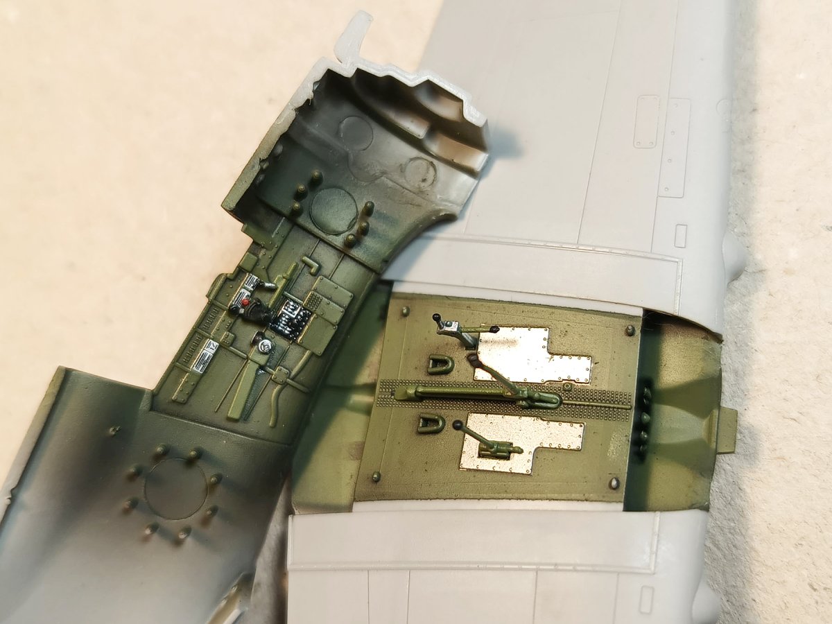
The wings
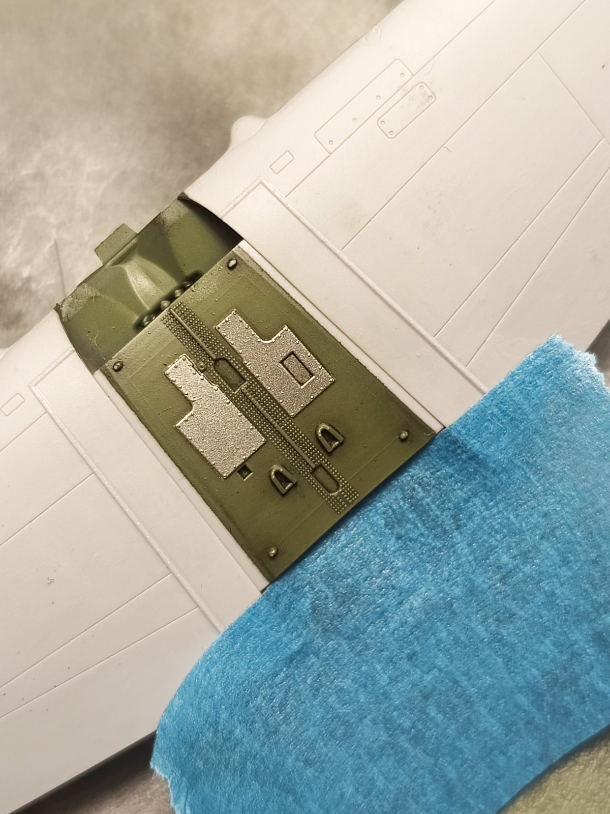
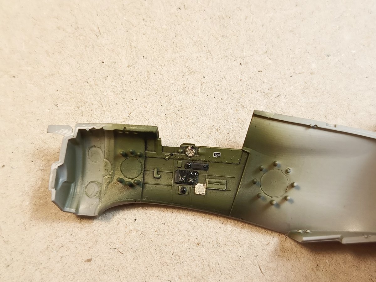
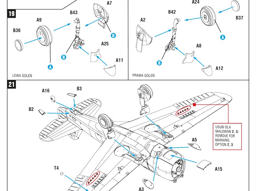
I start the model by gluing the wings together including the wheel wells. It is much easier to do the wheel wells covered by the canvas cover. Simply put the appropriate part there – the left and right are marked with the letters L and R. If you decide to make the wells without the cover (it looks very three-dimensional and impressive!), remember that the folding part forming the side walls and spars requires more attention, but it is absolutely not beyond the abilities of the average modeller.
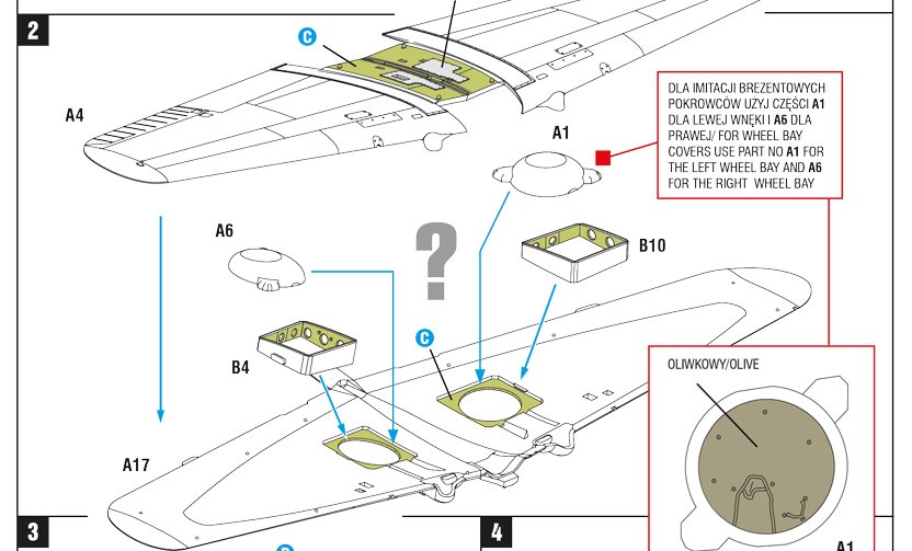
It is worth taking care from the very beginning to thoroughly clean the mating surfaces of the wing halves from the remnants of the sprue gates, so that the assembly is cleaner and requires practically no filling. Also check the instructions to make sure you don’t need to sand down some of the bomb rack parts – some planes had the rear stabilisers of the bomb tails removed.
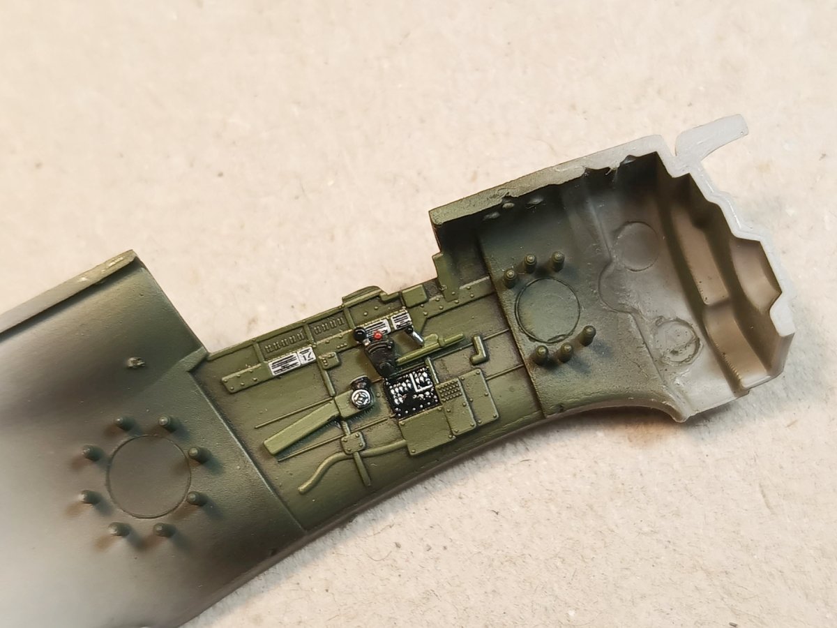
Cockpit interior
The cockpit floor is on the central part of the wing. Paint and glue the levers and sticks to it – the flash at the bottom of the control stick is not worth removing, it will not be visible in the depth of the cockpit. You just have to be careful afterwards not to break these delicate parts when assembling the fuselage with the wing.
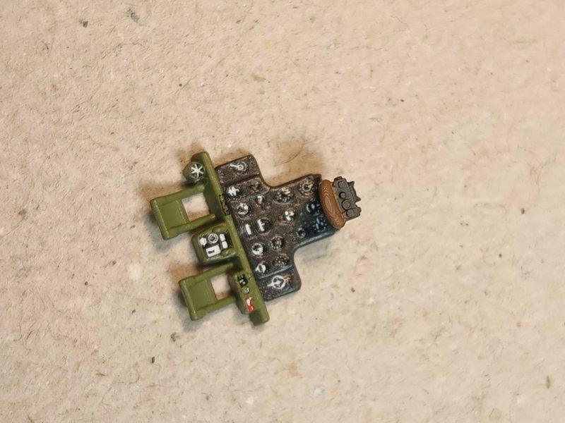
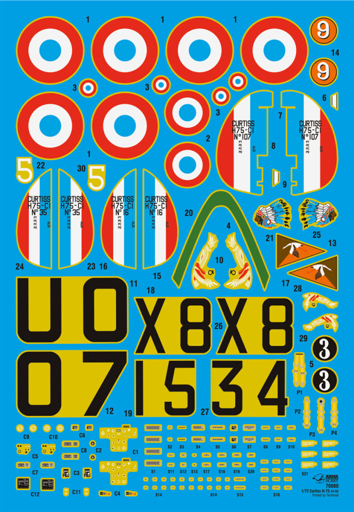
I then paint the interior of the cockpit and all the details separately in Curtiss yellow-green. I only apply the decals to the interior after painting the details with black and silver. The decals create a fantastic effect and add 100% detail saturation. Pro tip: sand the two trim wheels in the B47 part slightly, then the surface will be free of the roundness left by the milling on the edge of the wheels, it will be easier to put the round decals on such trim wheels, use a lot of decal Sol liquid on these decals either.
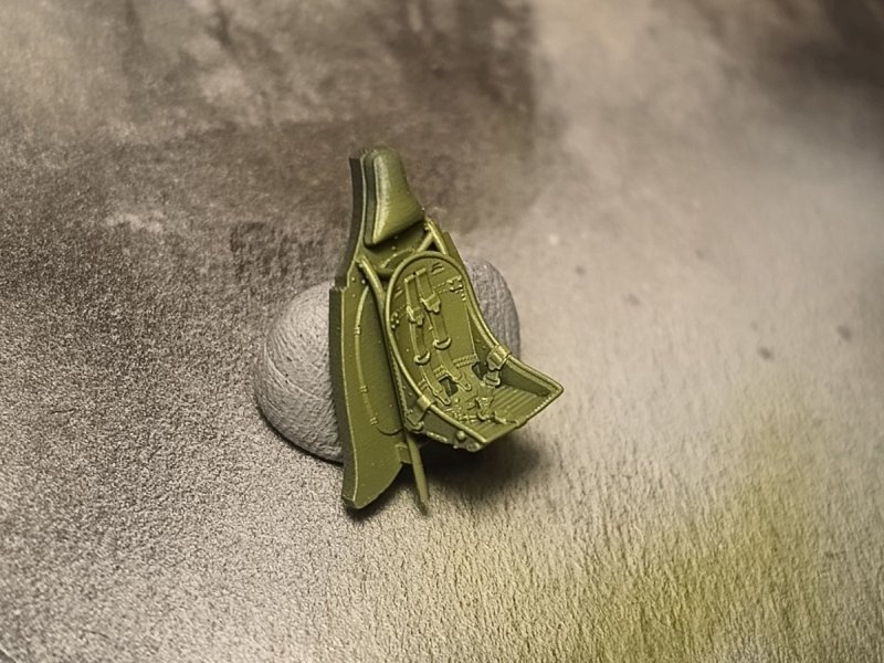
I glued the seat with bulkhead and instrument panel into the fuselage after painting and applying decals – this can be done before or after gluing the fuselage halves together. The photo shows the seat printed from the 3D file for self-printing that comes free with every model kit.
Fuselage-engine joint
As I wrote in the introduction, in the Curtiss fighter, the radial engine and the machine guns above it and the combination of all this with the fuselage has a rather complex shape. It was a fascinating design: when the inline engine was attached to the same fuselage, the famous P-40 was created!
When designing this model kit, we decided to reproduce these shapes and details as faithfully as possible. Therefore, we opted out of simplifying the assembly, and instead of having two fuselage halves from the tail to the engine, we designed slightly more parts there. Assembly therefore requires a little more attention, but this will be repaid by the rich, lively appearance of the finished model.
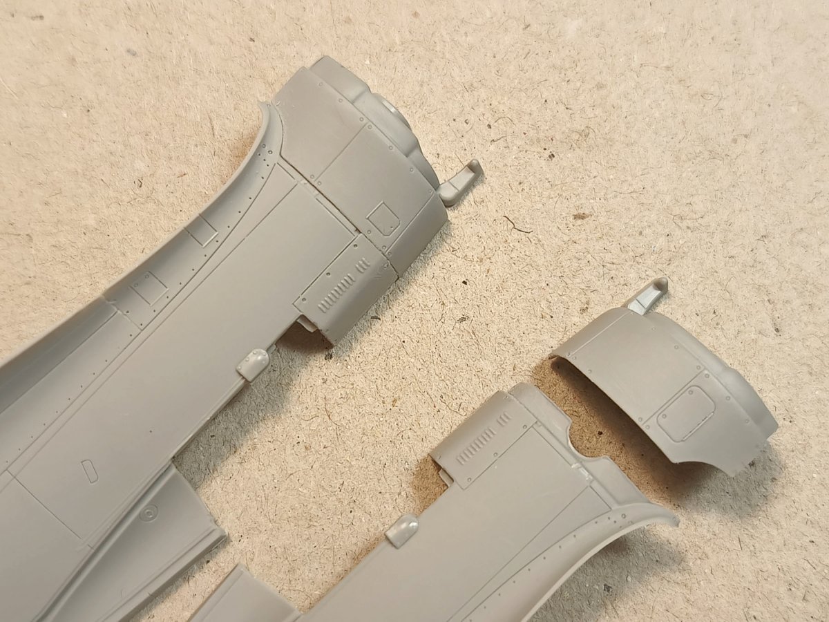
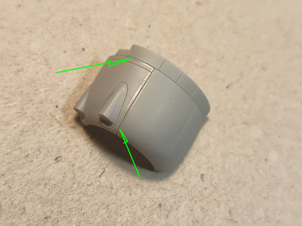
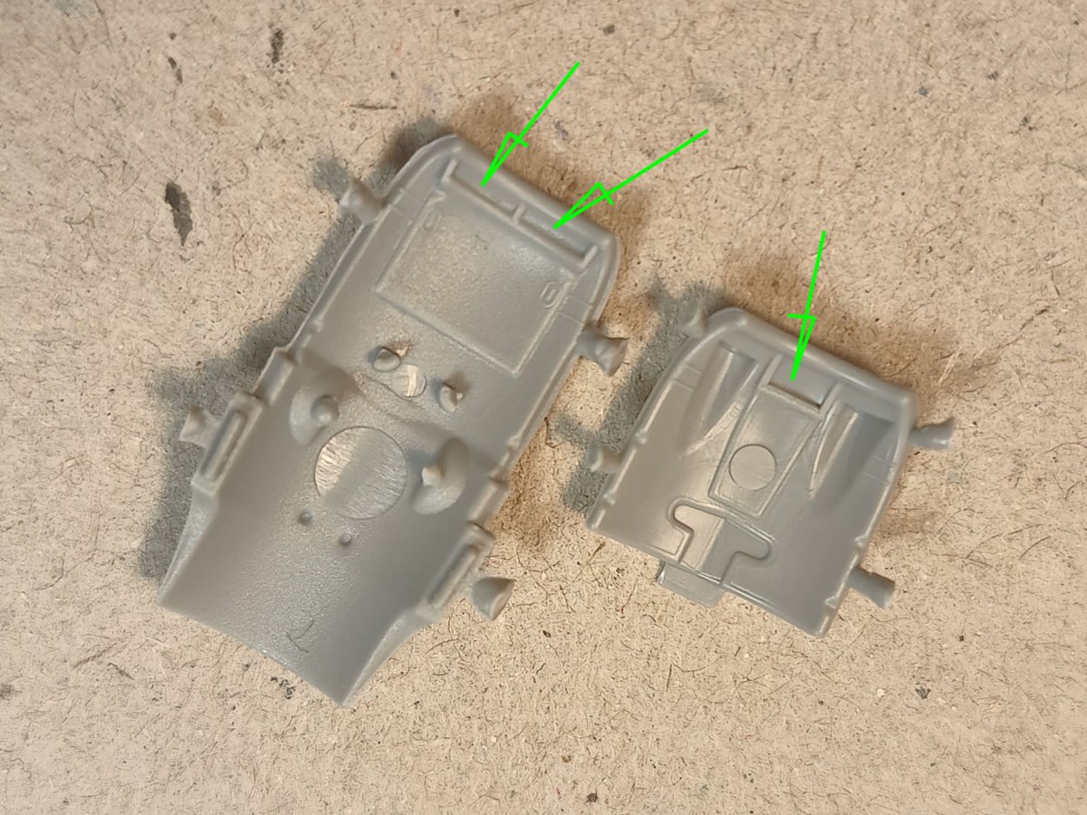
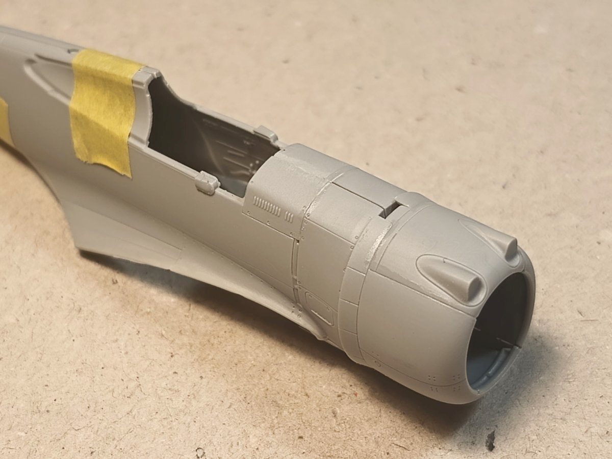
Some care is required to properly align the fuselage halves with the ‘behind the engine’ section. In some situations, parts 20 and 21 can ‘fall in’ too deeply at the joint with the fuselage halves, creating an unnecessary step in the side. A good way to make them fit is to attach these parts before gluing the fuselage together. Simply glue part 21 to part 10 and part 20 to part 23. Take care to ensure alignment at the top and bottom of the fuselage side so that there is no step in the areas marked with arrows in the photo below.
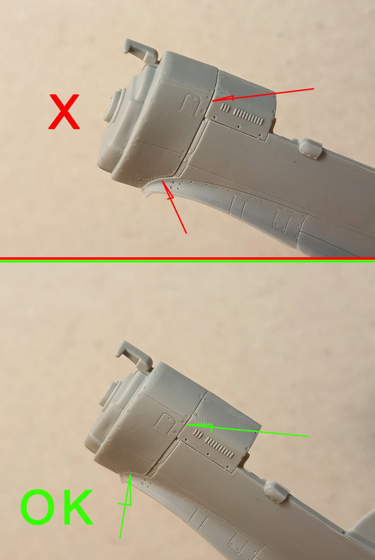
Don’t worry if a small gap (marked with an arrow) develops between parts 20 and 21, just fill it with CA glue (it won’t sink in, ordinary putty can over time).
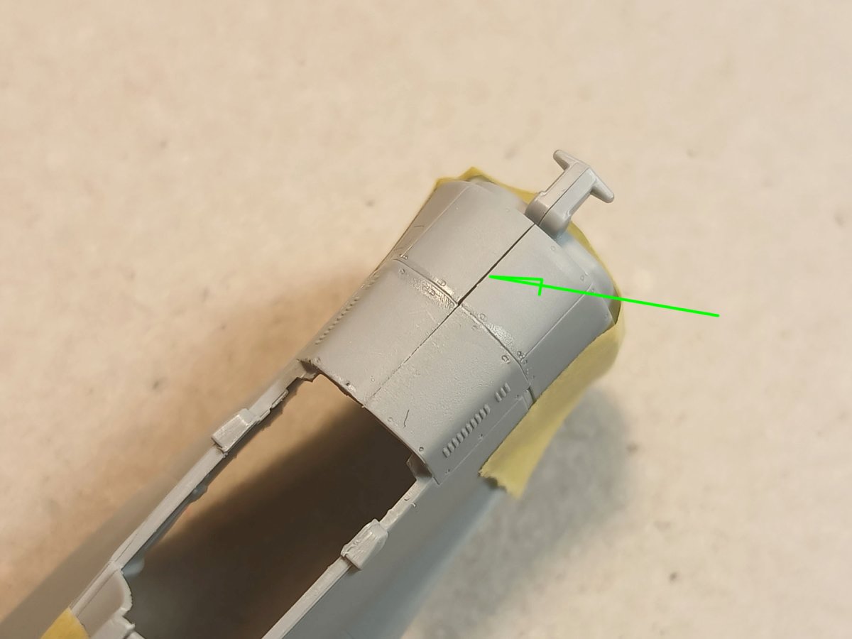
On the top of the fuselage in front of the windscreen, there may (but need not) then be a small step, which is easily removed by sanding a section in front of the windscreen. Anyway, in my opinion, it is a good idea to do each module of the model at the ready, with the surface finished, cavities filled and lines re-scribed after gluing. The final assembly can then be practically clean (and you might even be tempted to have fun with painted and decaled modules as Luftraum46 did on the Mustang).
Wideo: Budowa modelu w dwóch częściach? Eksperyment Krisa „Luftraum/72” Siebera
You just have to remember to check whether the air vents in front of the windscreen need to be sanded smooth on the aircraft you are building. Some planes had them and others did not.
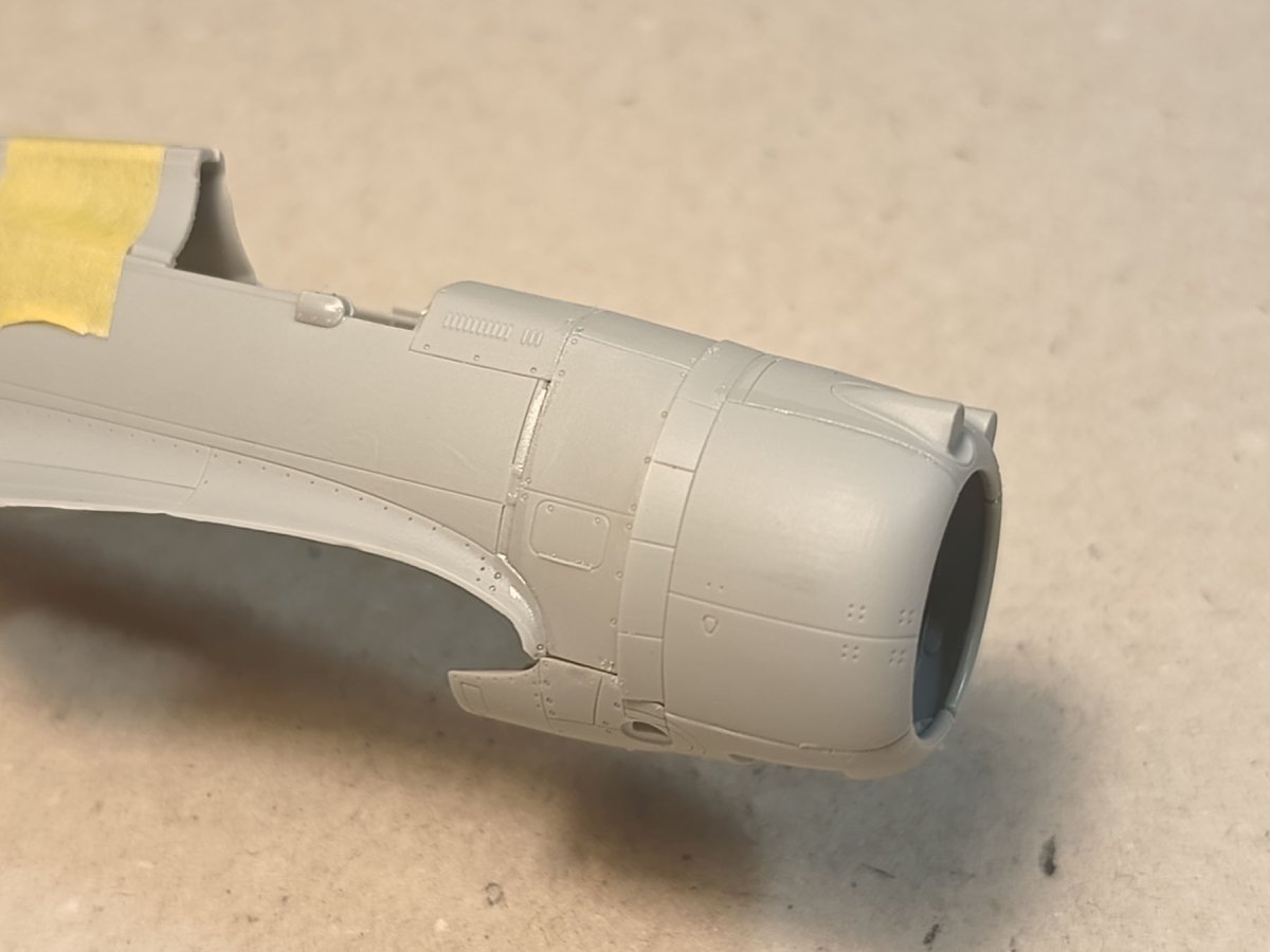
Engine cowling
I assembled the engine cowling separately, apart from the whole airframe – different from the instructions. Of course, if you build as in the instructions it will be fine too. It is simply important to align the top of the cowl with its sides.
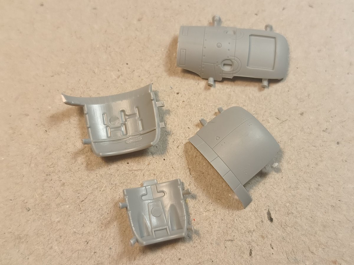
After cleaning the injection gates, I glued both sides to the top section taking care to ensure the continuity of the cooling flaps with the cover on the top section.
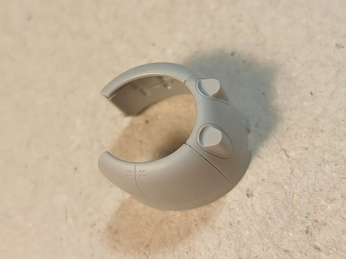
Once the glue has caught well, the lower, longer part of the cowl can be positioned. We try to align the bottom with the sides as well as possible and fill any gaps with micro drops of CA.
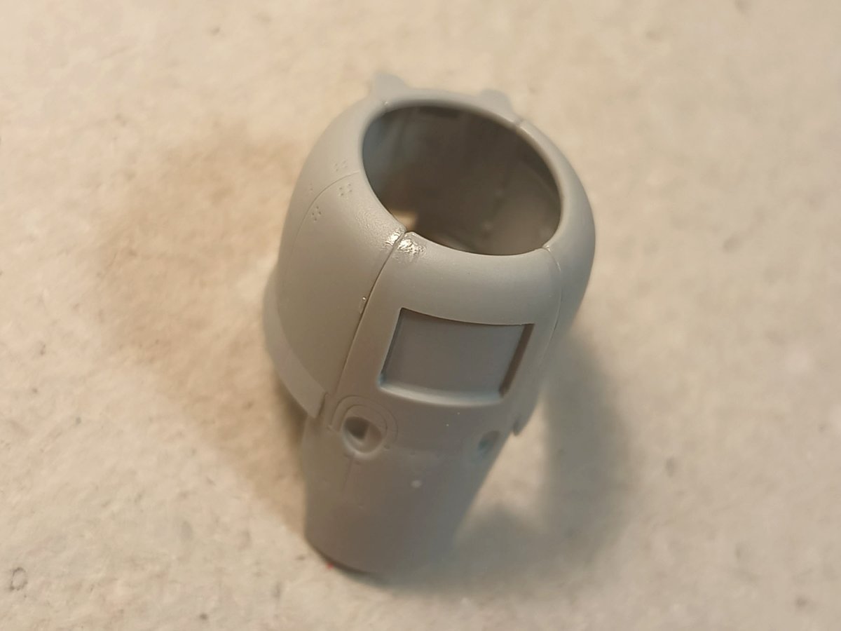
After sanding and if necessary correcting the panel lines, the lower air intake can be glued on. It’s worth noting the detailing inside the engine cowl. Both top and bottom are marked with the inner air intakes. It is a good idea to highlight them with black wash after painting.
I put the cowling prepared in this way aside.
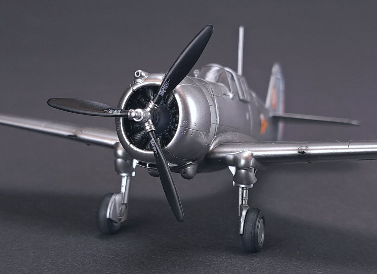
The engine
The engine looks very nice and is easy to assemble – we designed the valve pushrods (“sunshine”) so that cutting away from the sprue is easy. We paint the engine rows, washing and gluing them together, then gluing the painted “sunshine” on. The engine looks like the real thing.
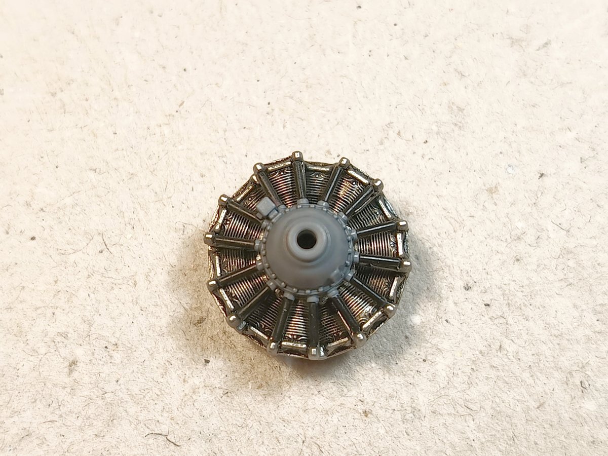
My engine in the photo does not yet have a wash on the grey crankcase. This will bring it even more to life. Of course, an advanced modeller will still add spark plug wiring.
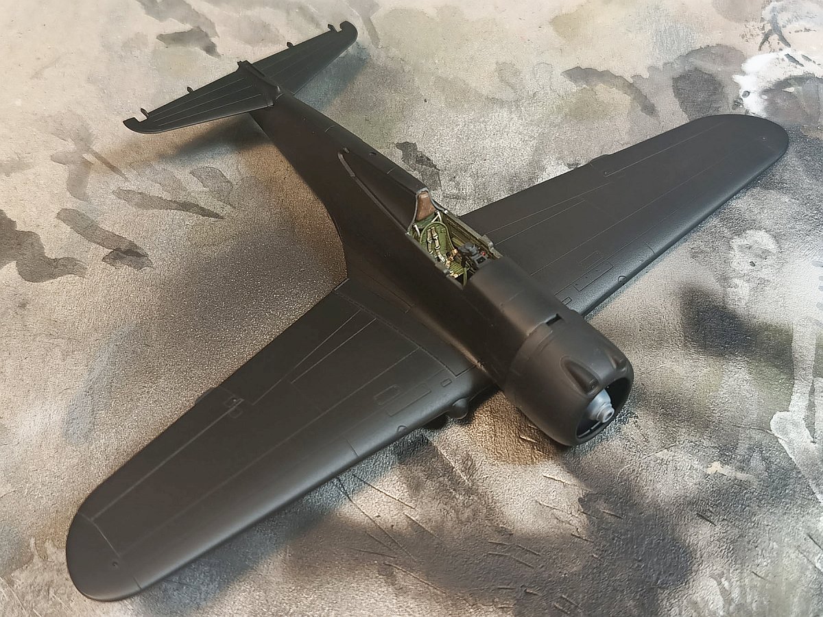
Wing-fuselage assembly
Before attaching the wings to the fuselage, it is a good idea to clean up the bottom edge of the fuselage-wing transition in the fuselage halves. This will ensure that no putty is required to assemble the wings, a few small drops of thin glue will give a perfect fit.
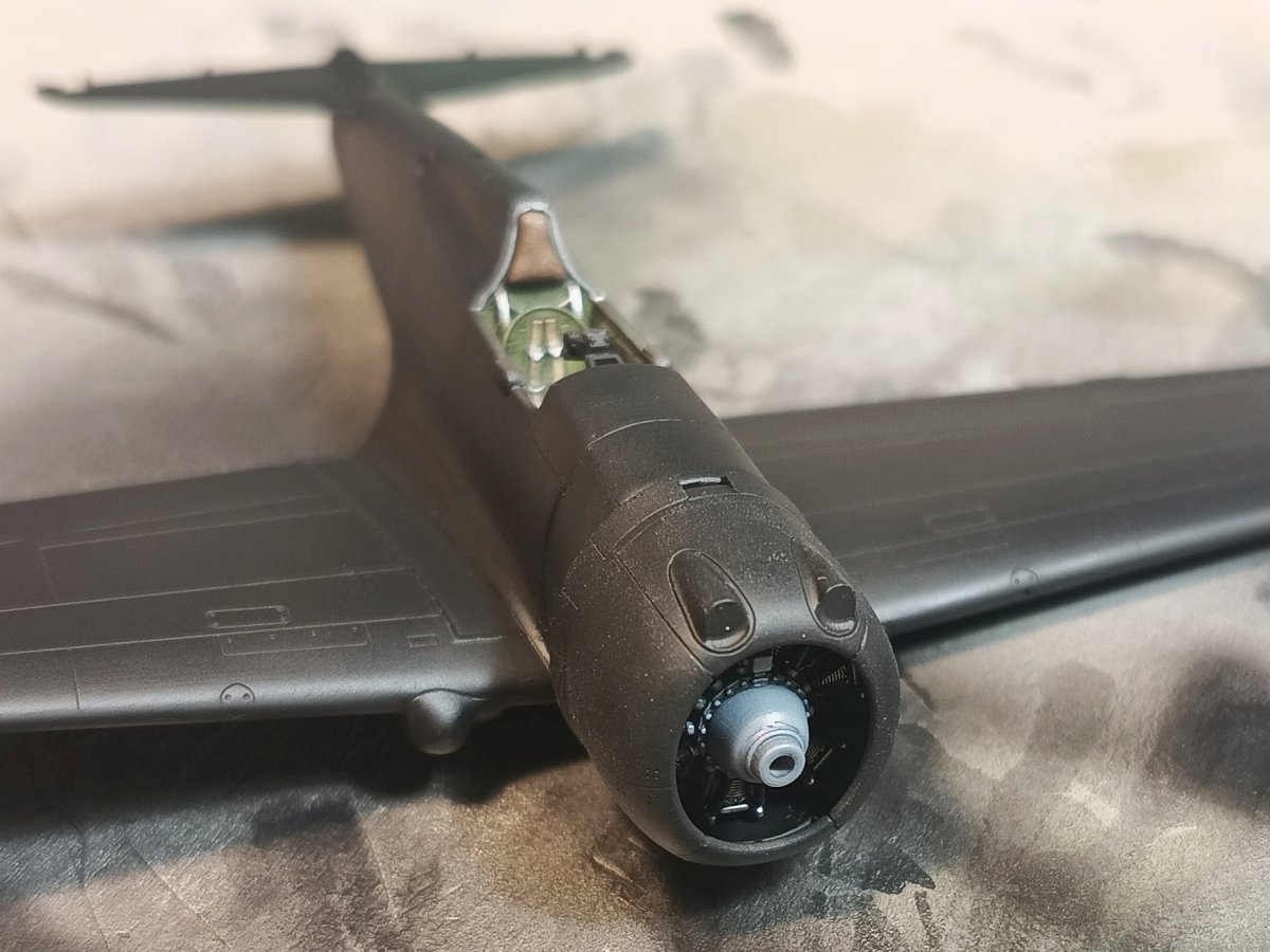
If you assemble the engine cowl according to my description, only now put the cowl on – with a click – on the assembled fuselage-wing assembly and fix it with a bit of thin glue at the bottom and top.
The cockpit
When cementing the glass behind the cockpit (parts T2 and T3), I advise you to use minimal amounts of thin glue, the parts are close together and will suck the glue capillarily around the perimeter of the joint. The joint area, although made of clear plastic, will not be visible as it will disappear under the paint in the finished model. Before gluing them on, don’t forget to paint the interior there aluminium and apply the S3 decals.
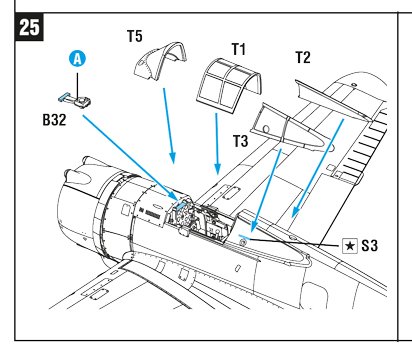
Do not over-sand the windscreen on the underside either, then you may find that you have removed too much plastic and you get a gap between the fuselage and the glazing, or the glazing ‘sits’ too low. The sliding canopy fits well in both closed and open versions, but don’t push it too hard, over-pressured clear plastic can get foggy.
The undercarriage
The assembly of the undercarriage needs no comment, only the front rounded covers (A11 and A12) may be easier to attach already when the undercarriage is glued to the wings.
The assembly of the other components requires no comment.
These are my notes for building Arma Hobby’s latest model, the Curtiss H-75A. You can build it according to the instructions, but my tips can make things easier in the more difficult moments. It is a beautiful aircraft and the model is very rewarding and I look forward to your galleries.
Check also:
Curtiss H-75 A1/A2 – plik z detalami do samodzielnego wydruku 3D
Wanted to be Philanthropist, statesman and patron of the arts. Temporarily focused on developing scale model production in Poland. Co-founder of Arma Hobby. Designer of kits: TS-11 Iskra, PZL P.7a, Fokker E.V, PZL P.11c, Hawker Hurricane, Yak-1b, Wildcat, P-51B/C/D Mustang and 1/48 Hurricane.
This post is also available in:
 polski