
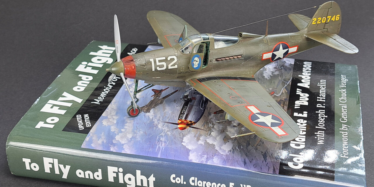
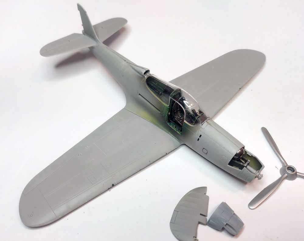
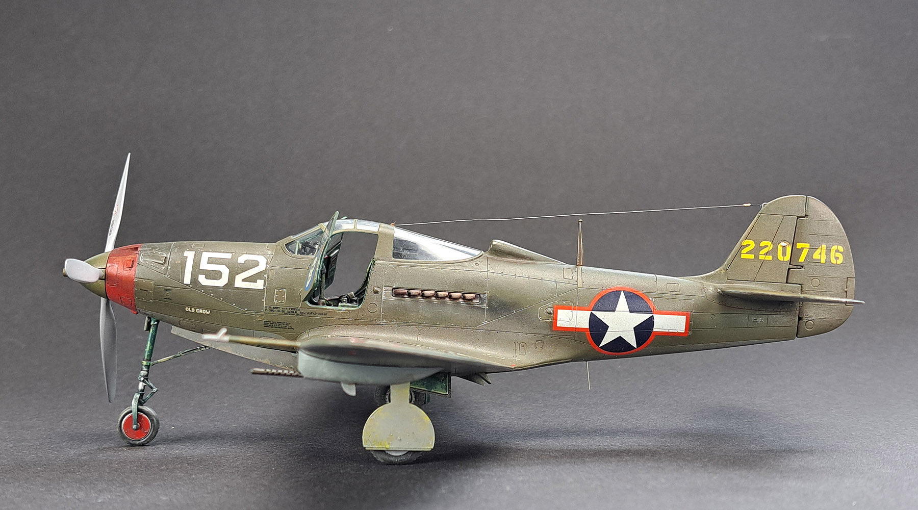
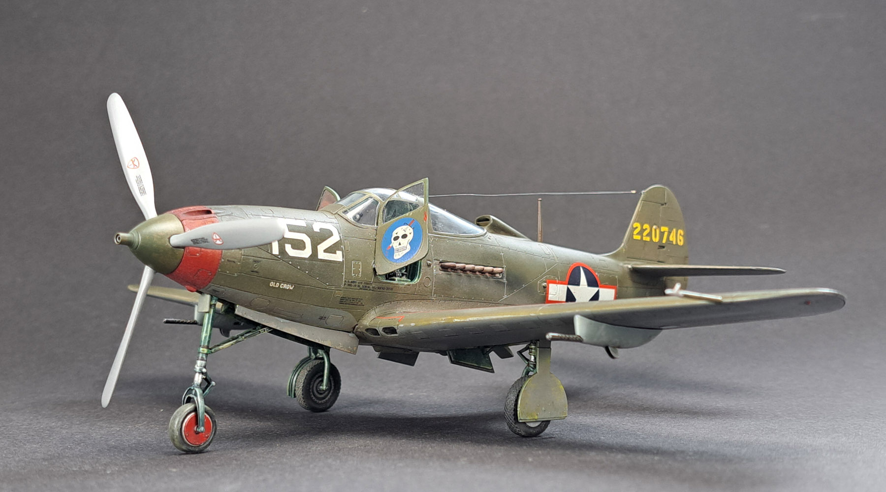
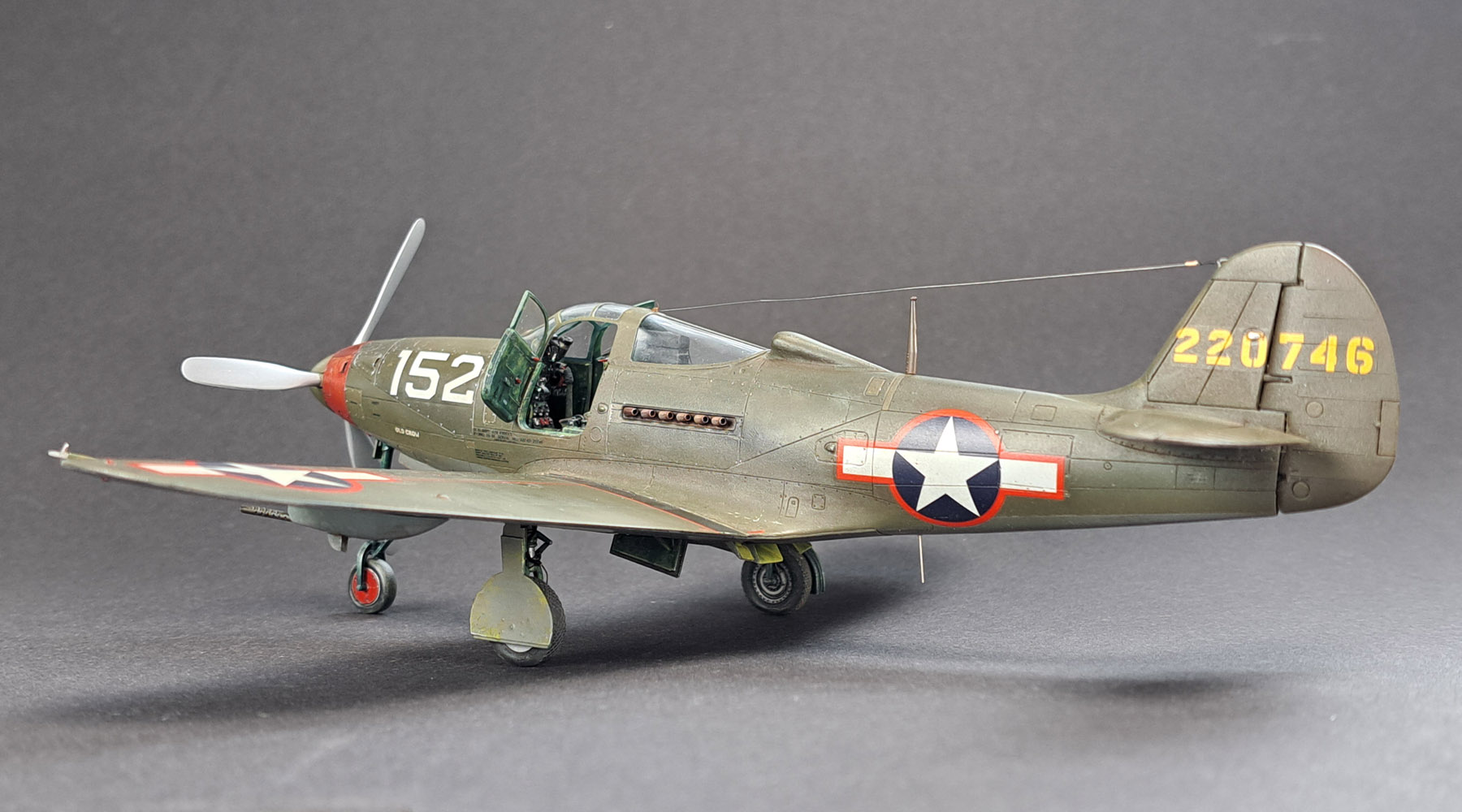
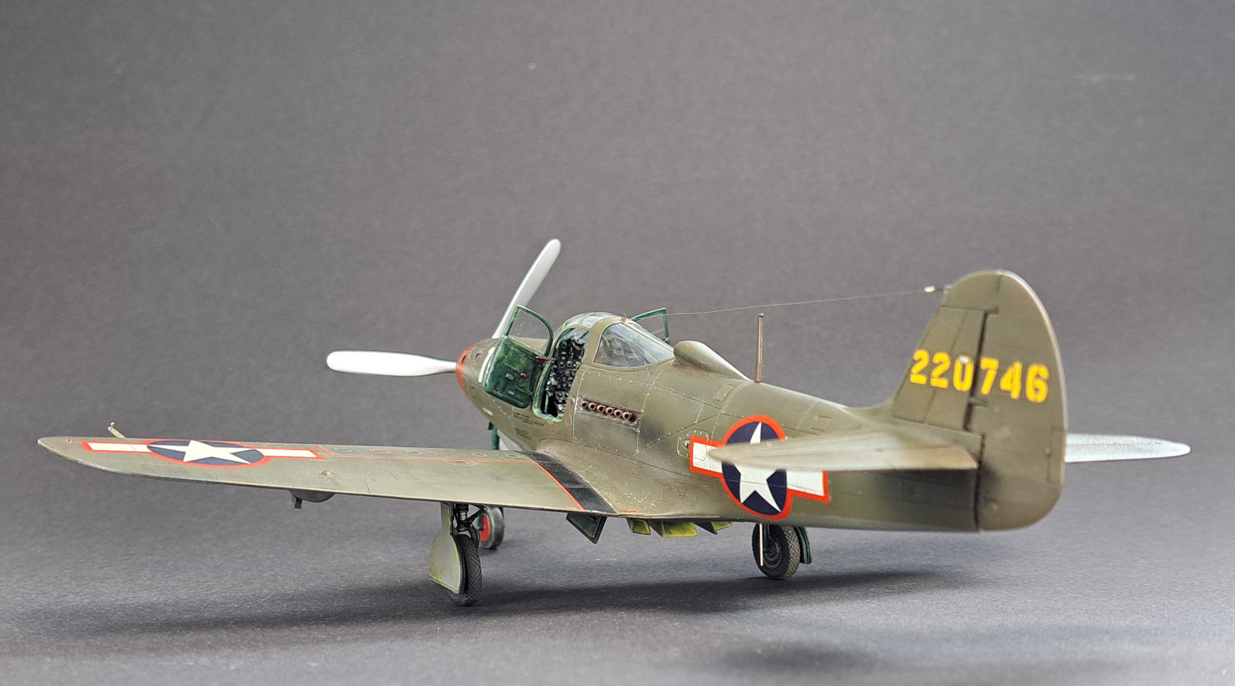
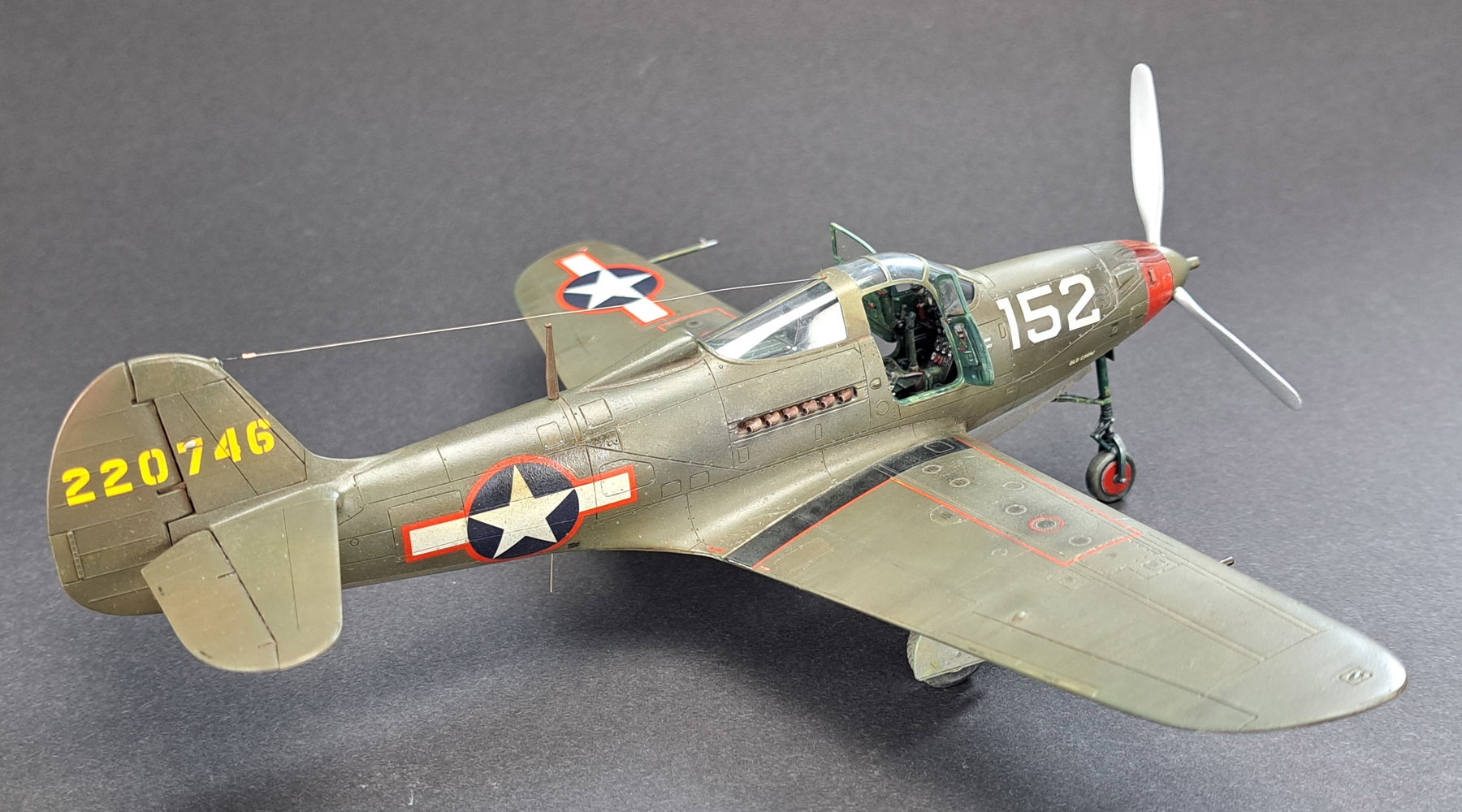
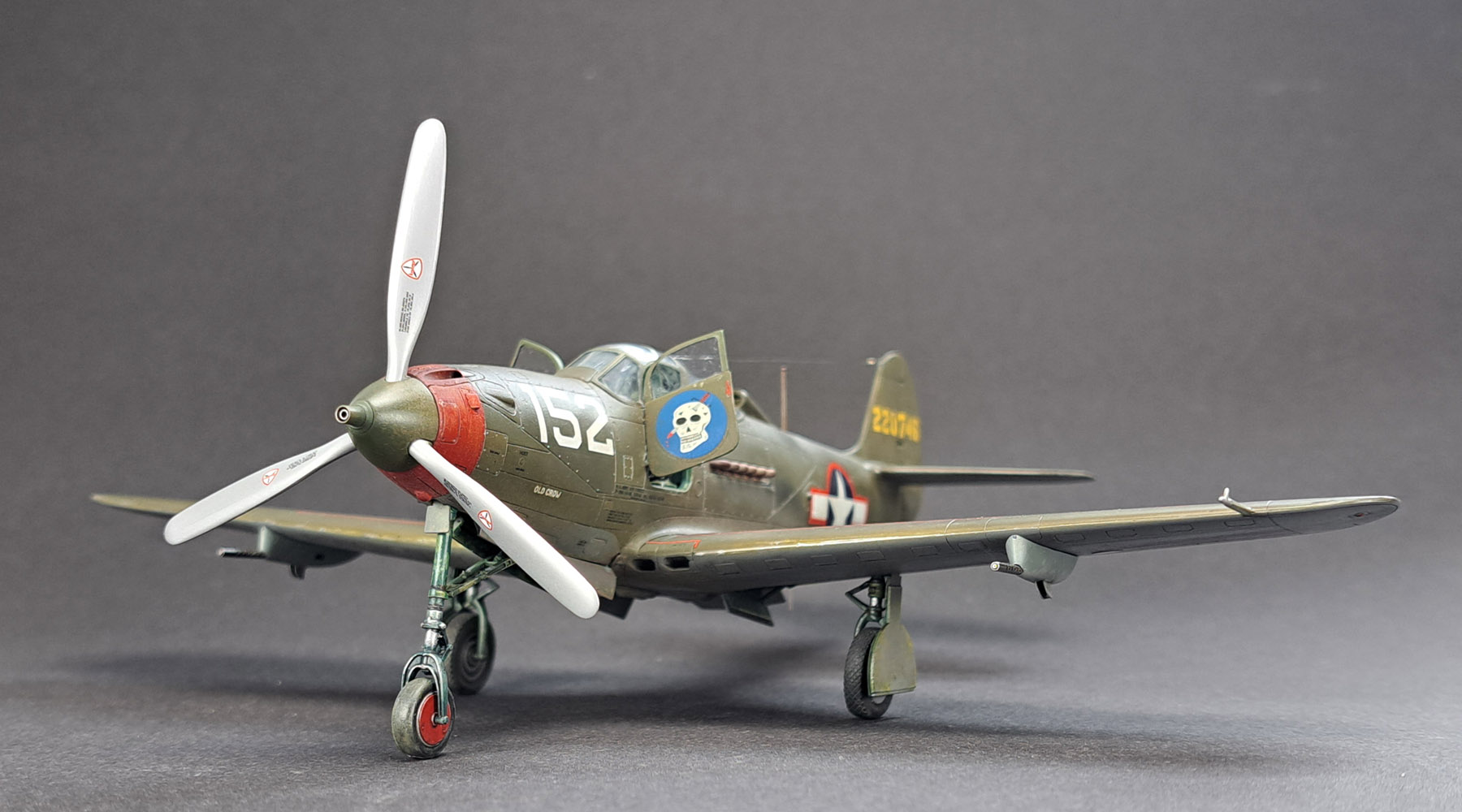
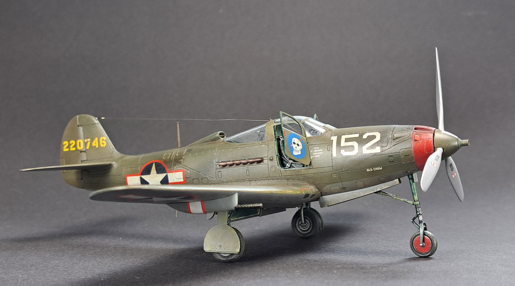
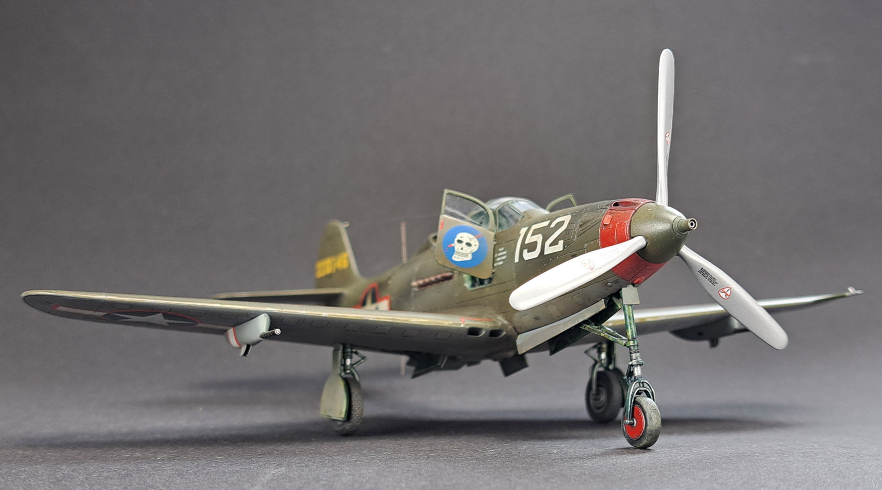
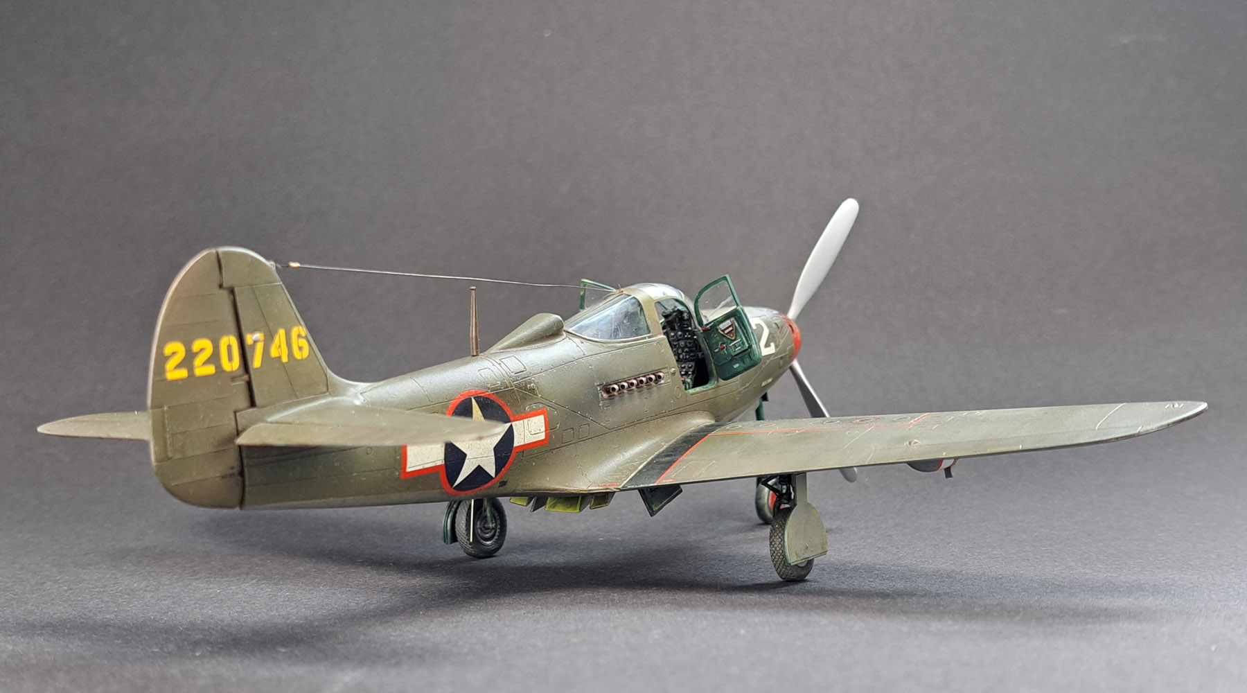
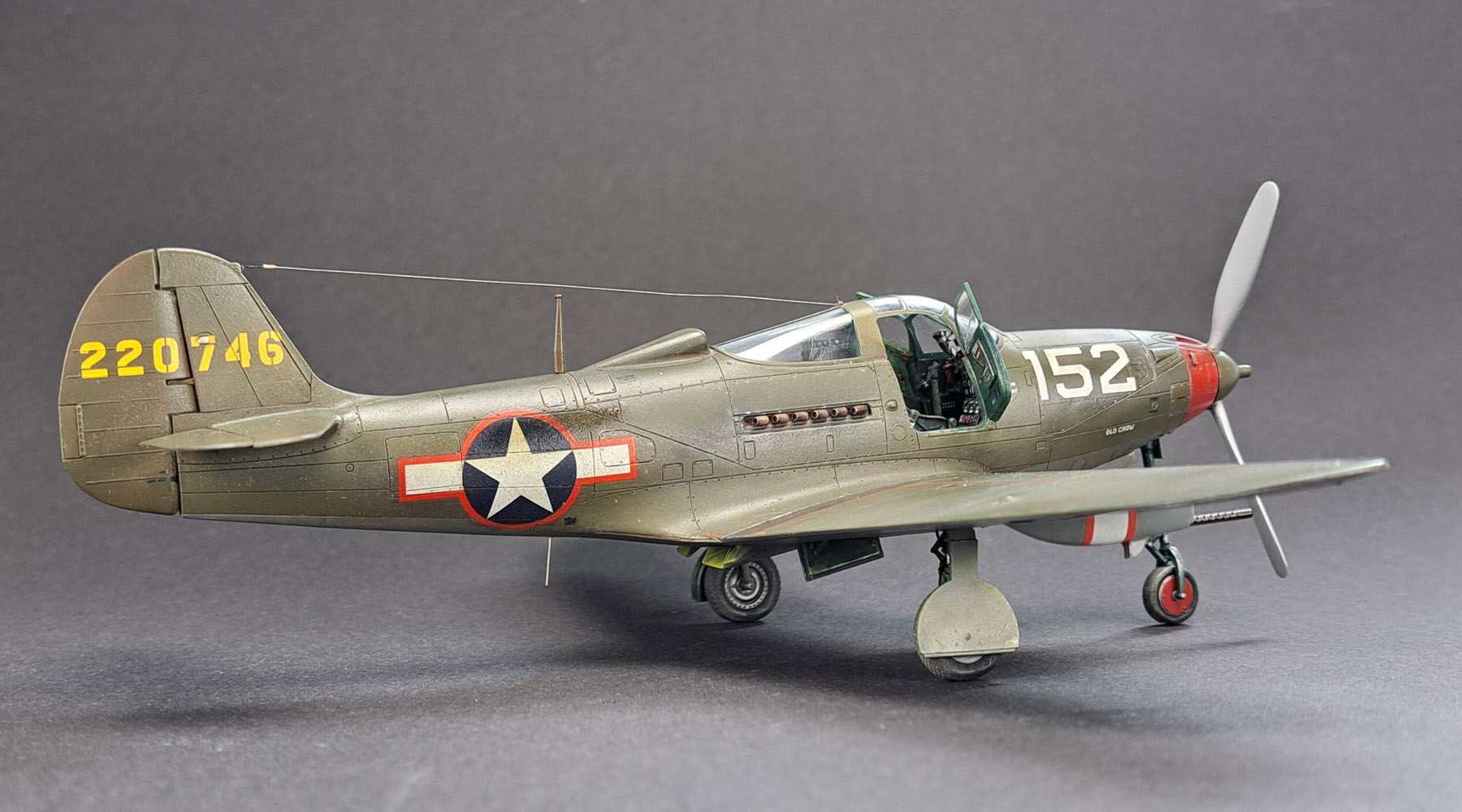
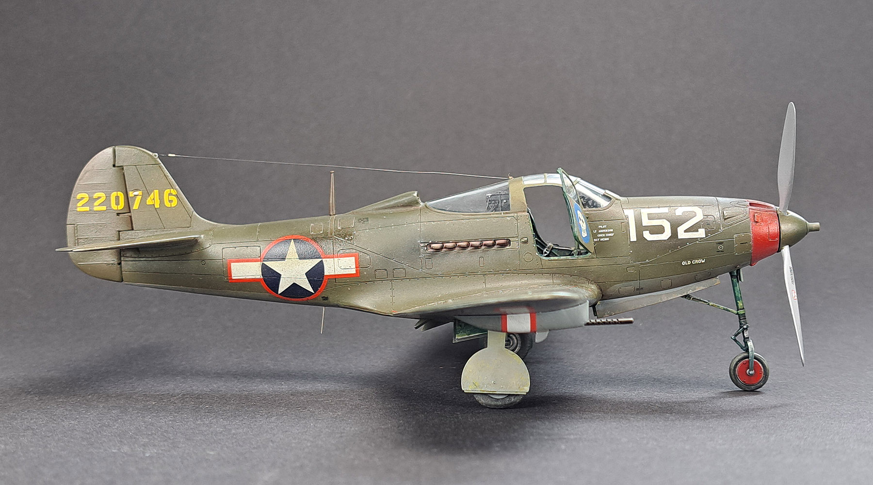
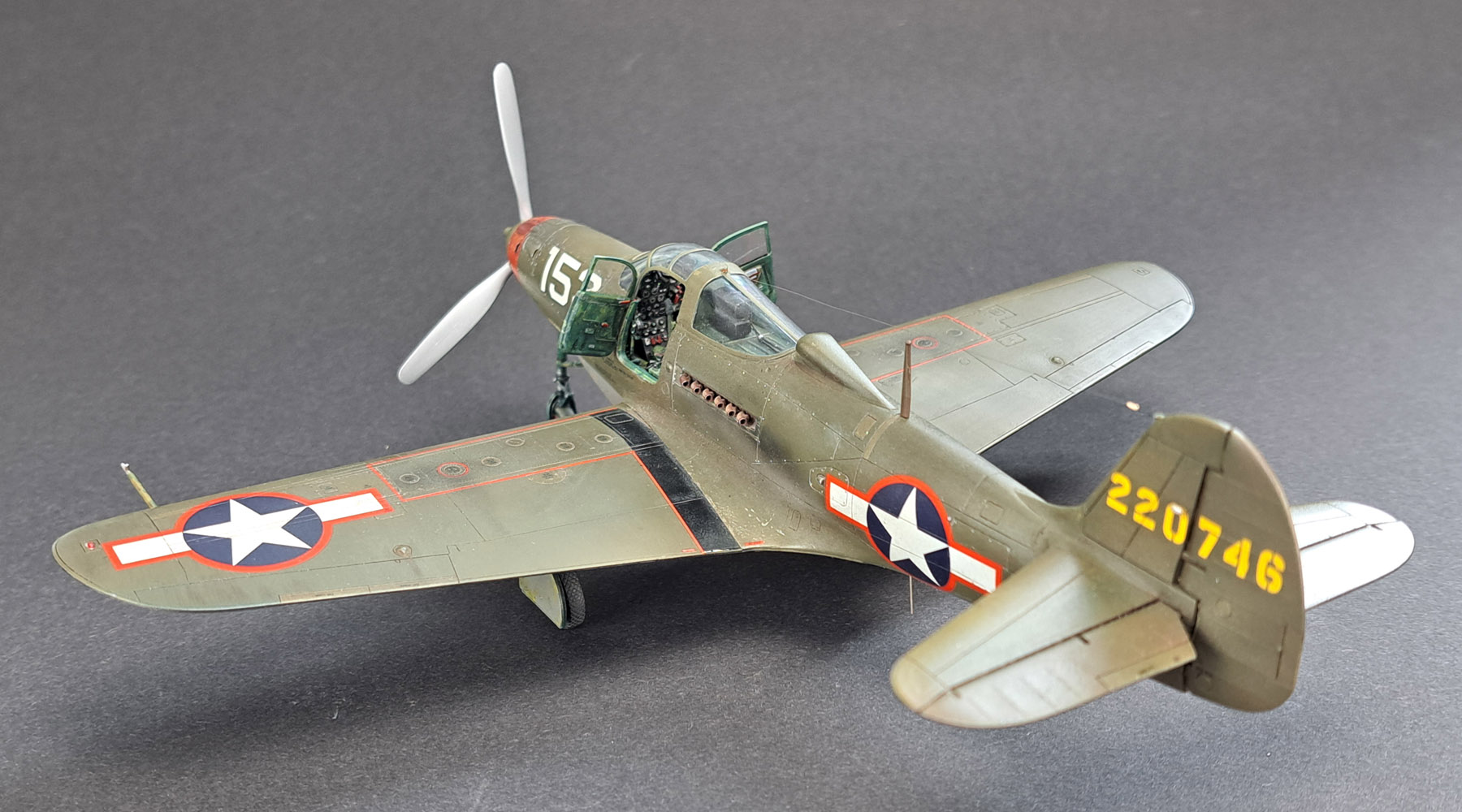
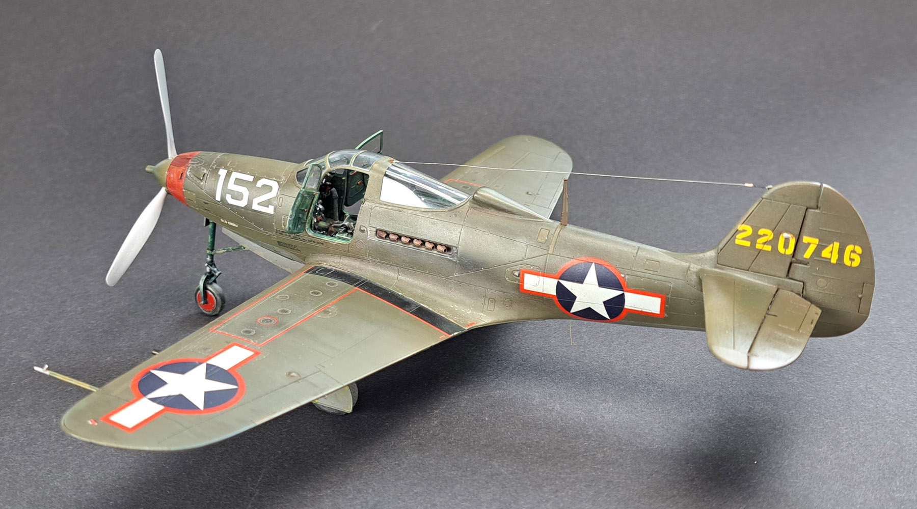
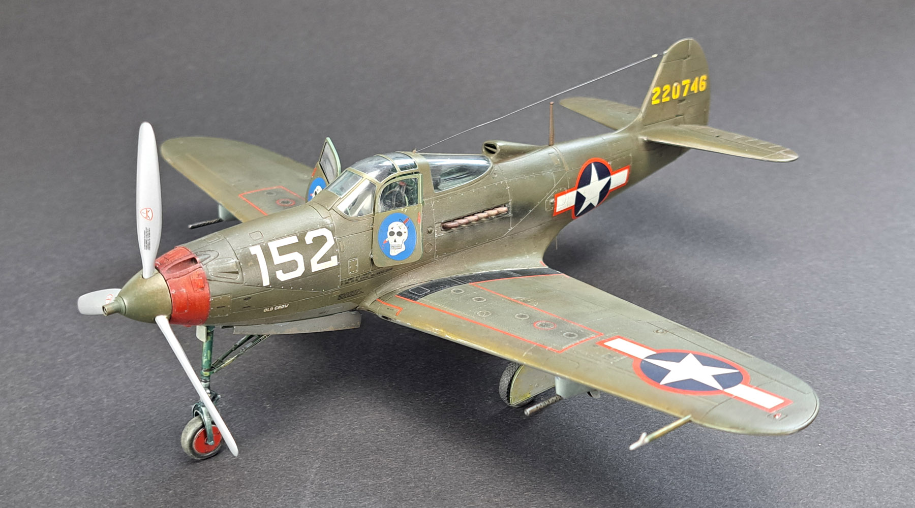
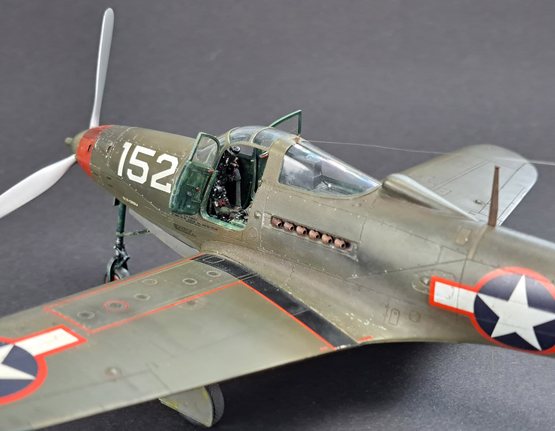
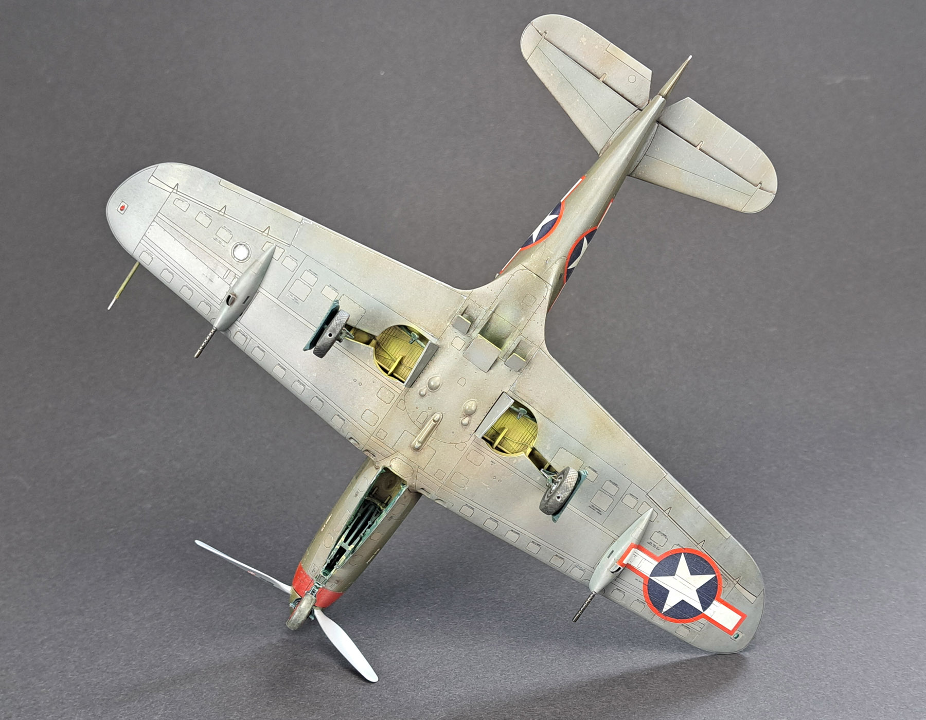
I present the first completed model of the Airacobra from Arma Hobby on a 1/48 scale. The model was assembled “almost out of the box,” with the addition of 3D accessories and a few minor details that I wanted to add.
The model represents Clarence “Bud” Anderson’s aircraft from the summer of 1943 in sunny California. Check out the article discussing the appearance of this aircraft.
A Few Modifications
For the assembly of the model, I used the following 3D accessories from files available in our shop:
- 48012-3D P-39/P-400 Exhaust Pipes 1/48 3D-File
- 48015-3D P-39/P-400 MG barrels 1/48 3D File
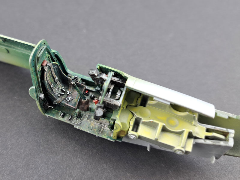
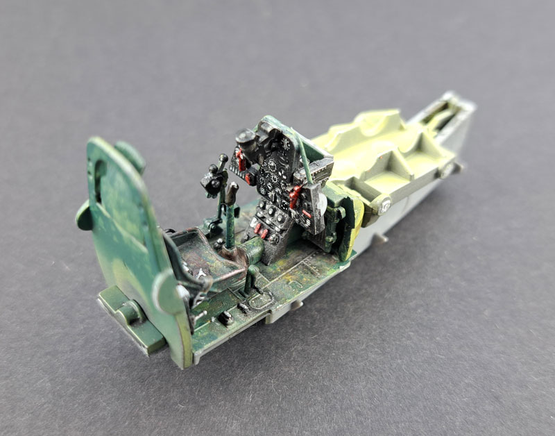
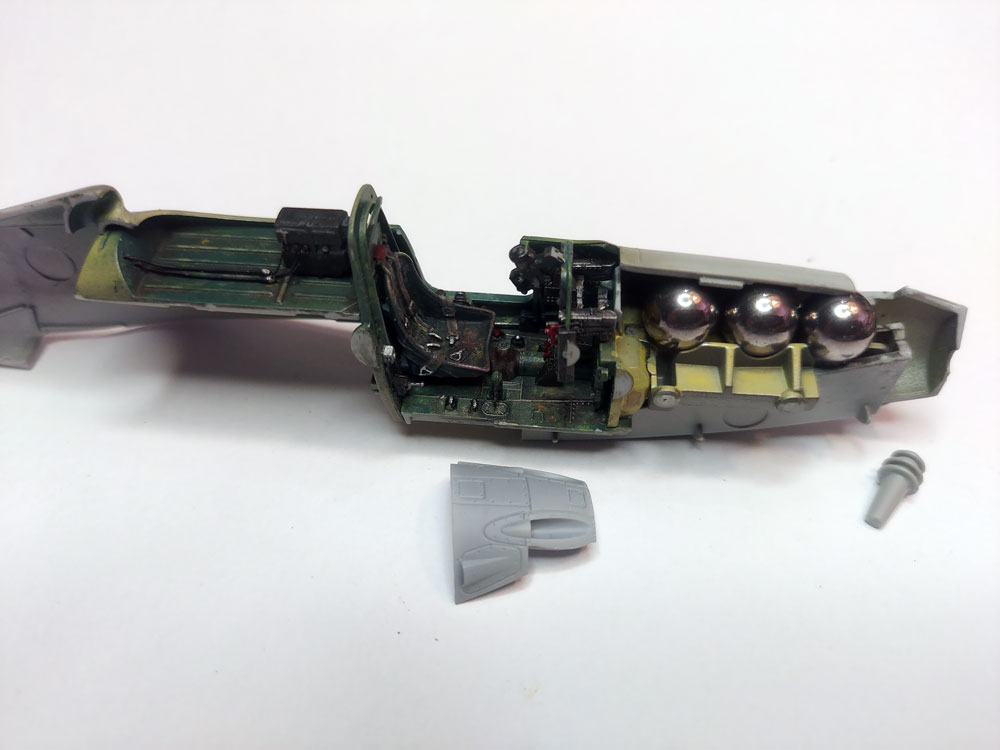
- 48016-3D P-39/P-400 Cockpit details 1/48 3D File
- 48017-3D P-39/P-400 Front of the fuselage with weapon slots 1/48 3D-File
- 48018-3D P-39/P-400 Nose wheel 3 types 1/48 3D-File
- 48019-3D P-39/P-400 Front landing gear leg 1/48 3D-File
- 48020-3D P-39/P-400 Main wheels with diamond tread 1/48 3D-File
Additionally, I added:
- Radio wiring on the fuselage spine and jack box in the cockpit
- Wire antenna (0.05 mm wire Shelf Oddity)
- Antenna under the fuselage (Albion Alloys tube)
- Brake lines and fuel lines in the main landing gear bays
Assembly Notes
The model moulds are made with a slightly different technology than previous ones, resulting in minor tolerance issues with positioning elements. The parts fit precisely in the design, but the positioning pins turned out to be too large during mould preparation. You can resolve most by cleaning the joint edges and sanding down the oversized positioning elements.
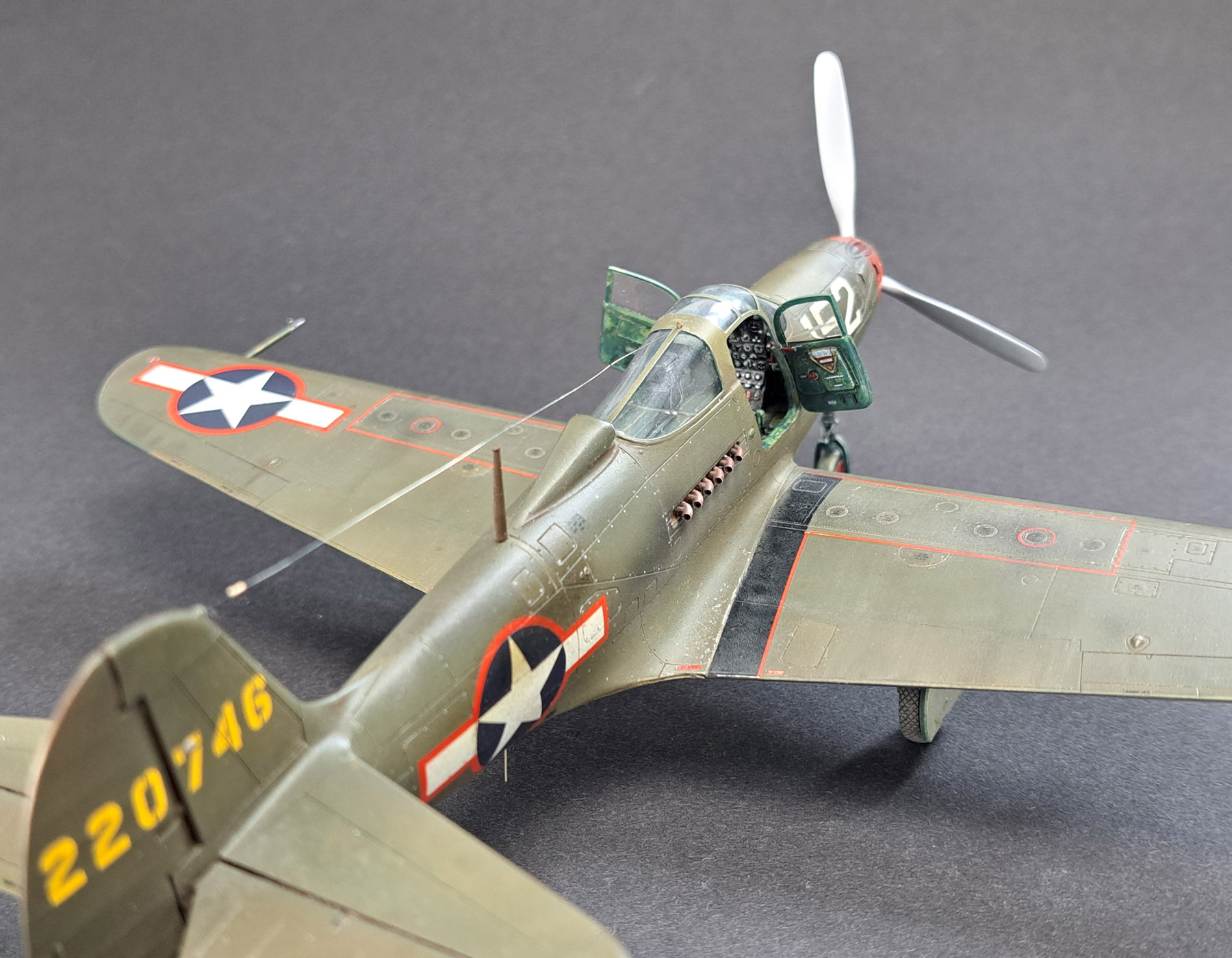
Cockpit:
- Thoroughly clean the joining surfaces of the fuselage halves, avoiding paint contamination.
- The cockpit and front landing gear bay assembly is heavy after the balls are glued.
- Attach the bulkhead behind the pilot’s seat (A32) to both fuselage halves to maintain proper geometry for attaching the cockpit.
- If you are building the version with the armour plate above the pilot’s head (B67) and using the 3D seat, trim the top part of the pilot’s harness to fit the attachment on the plate.
- Divide decals into smaller sections to fit the panel’s contours more easily when applying decals to the instrument panel.
Fuselage Front:
- Remove unnecessary panels on the side of the armament bay and a small air outlet at the front.
- The small air outlets from the included 3D print attach surprisingly easily. Clean the glueing area and apply Tamiya Thin liquid cement. Grab the 3D detail with tweezers, detach it from the frame, and press it to the glued surface. It holds excellently after painting.
- Assembling the gun port cover (B59), you should ensure it fits well; you may add braces to its base.
Wing:
- Be careful not to cut off the small tabs on the centre part of the upper wing halves (C68).
- The walls in the landing gear bay should not touch the upper part of the wing.
- The joint between the top of the wing (C68) and the fuselage surface (B37/38) is overlapped, and the step is natural.
- The semicircular surface next to the main landing gear cover (B54/55) should have a natural gap around the arc glued to the wing (C89).
- Fill the sink marks on the wing’s upper surface (C68) with superglue; after it dries, sand it with flat sandpaper. After 24 hours, superglue will be too hard. I additionally protected the surrounding panel lines with masking tape to avoid sanding them off.
Landing Gear:
- The main landing gear wheels from the 3D print require drilling a larger hole, as they compress during printing.
- The nose landing gear (A13/B66) fits into place after cleaning the joint areas and does not require glueing.
Tailplane:
- It assembles nicely, but cleaning the joint between the fin (B56) and the left fuselage (B37) and reducing the protrusion connecting the vertical stabilizer to the horizontal stabilizer are required.
Cabin Doors (T1/2):
- For glueing in the open position, I suggest cutting a groove at the hinge point or drilling a small hole at the joint for better hold.
Propeller Spinner:
- Unfortunately, the fix for the sink mark on the spinner (B53) made by the tooling workshop is too large. Drill a hole in the propeller (C74) from the back or reduce the pin on the spinner (B53) with a larger drill bit, and the propeller will fit into place.
Decals
- Cartograf decals fit very well on the model’s details. However, they are soft, and care should be taken not to stretch them.
- The end of the star stripe on the machine gun pod represents a mirrored reflection. Cut off the red end of the decal and apply it in reverse. Then attach the end from the other side.
Photos: Marcin Ciepierski
See more:
Photos of the model
Modeller happy enough to work in his hobby. Seems to be a quiet Aspie but you were warned. Enjoys talking about modelling, conspiracy theories, Grand Duchy of Lithuania and internet marketing. Co-founder of Arma Hobby. Builds and paints figurines, aeroplane and armour kits, mostly Polish subject and naval aviation.
This post is also available in:
 polski
