
We present to you the new Arma Hobby kit, the F4F-4 Wildcat. Let’s see how we managed to process the design into plastic parts and how they build together. See, that’s impossible to design a perfect model, but we dare to try…
The Tooling workshop job was quite adventurous this time. The tooling of the new Wildcat model took a long time. Originally it was supposed to be released in June, and the final happened in September. The mould production process consists of several stages, and, unfortunately, each stage depends on the other person. The Summer holiday season and the Covid quarantines interfered with this multi-stage process.
Notes about the wings of the Wildcat F4F-4 model
Wings fell victim to the extended tooling process. During test shots, it turned out that the trailing edge did not cast to the very end. Simple solutions did not help, so we thickened each half of the wing by 0.05mm per side. However, we did not want to change the outer side where all the details are moulded nicely (panel lines, hinges, convex details. The second factor was the Summer break time that would not allow us to return to the EDM process. That is why we decided to make the wing thicker from the inside. We saved the wing surfaces, but the plug positioning the wing in the fuselage got thicker. To make it straightforward for modellers to assemble the model despite this feature, I will describe how to prepare the parts before glueing.
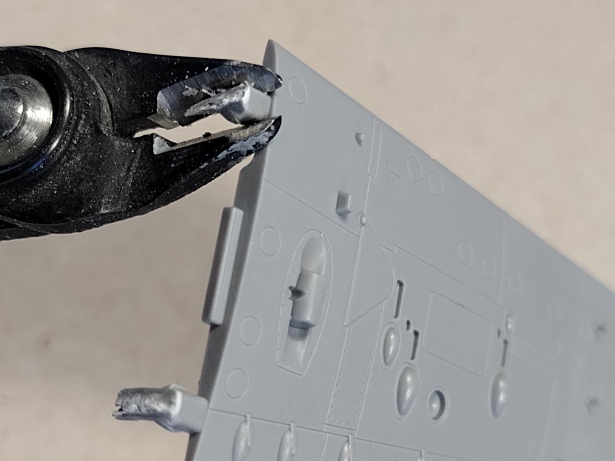
Wing, cut, clean and glue. The first move is to cut some of the wings out of the frames. It is good to do this with a margin so that the cut near the part does not damage the outer surface. With nippers, you can cut out the injection points on the joint’s surface between the wing and the fuselage.
You can see how the assembled wing halves look like before processing.

Note: To improve the wing thickness, we do not work on its lower half, because sanding this part will destroy the mounting pins and the position light on the tip. On the outer surface of the lower part of the wing, there are details that you can break easily (pylon attachment). That is why we should only work with the upper half of the wing.
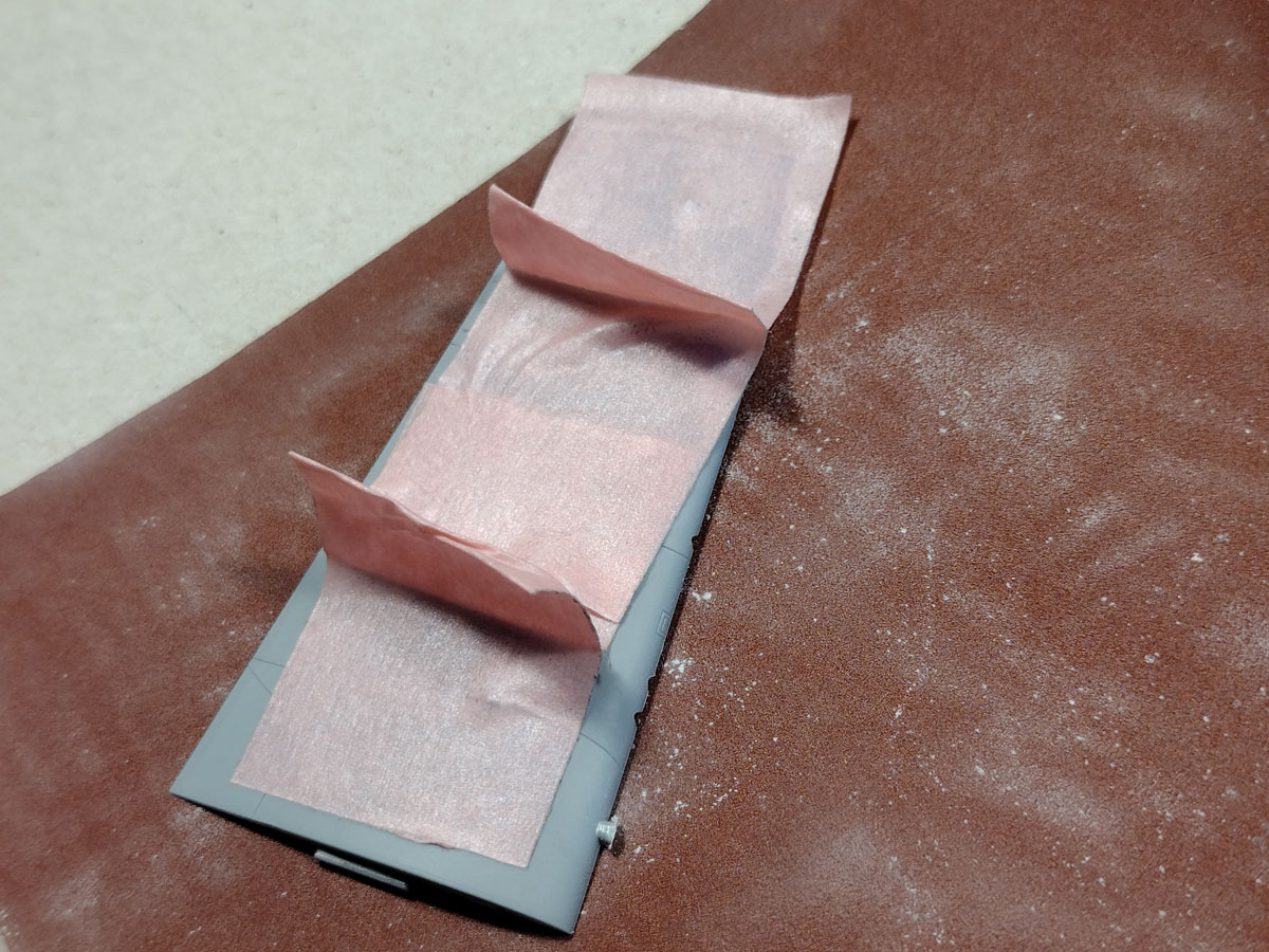
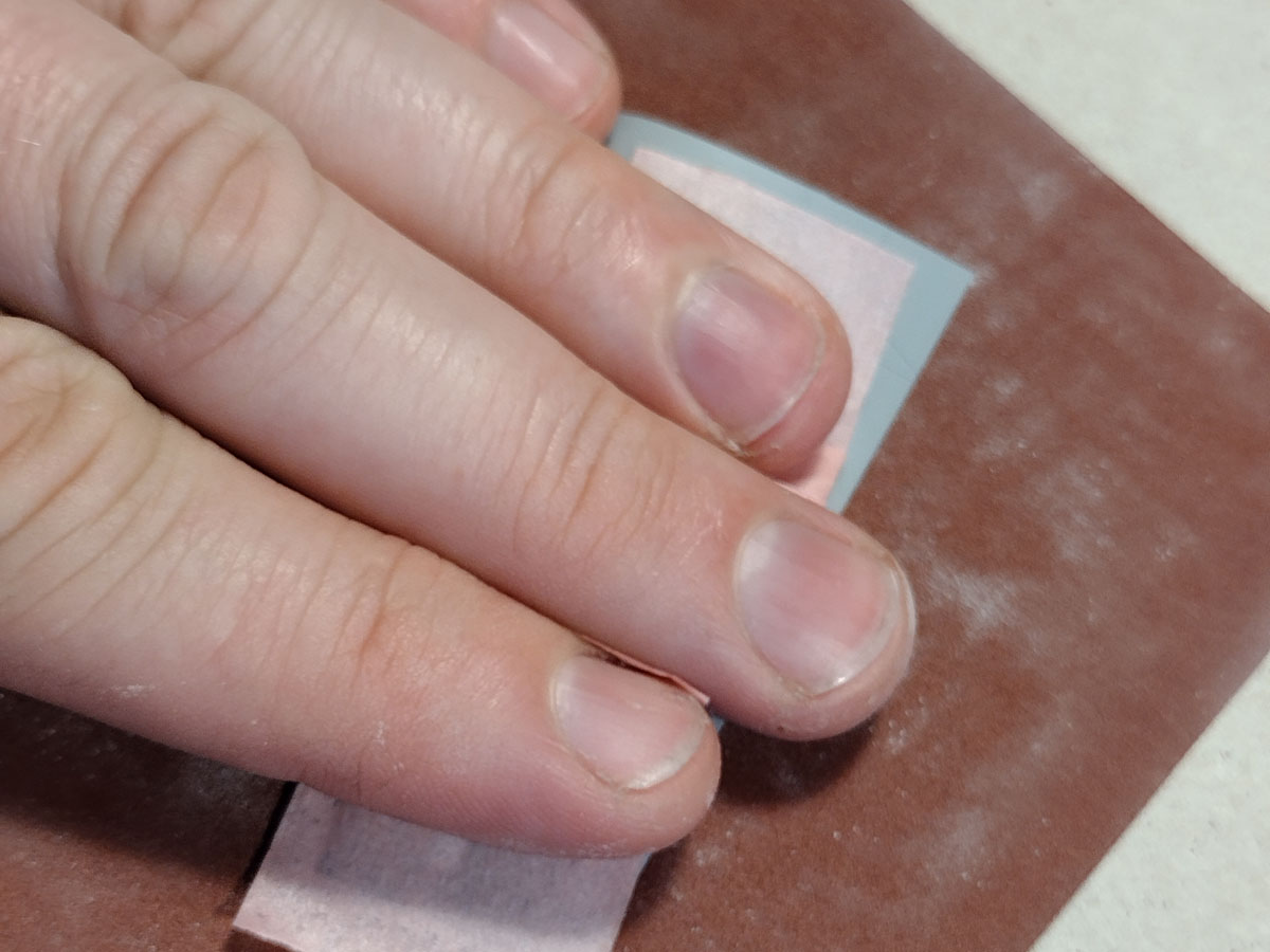
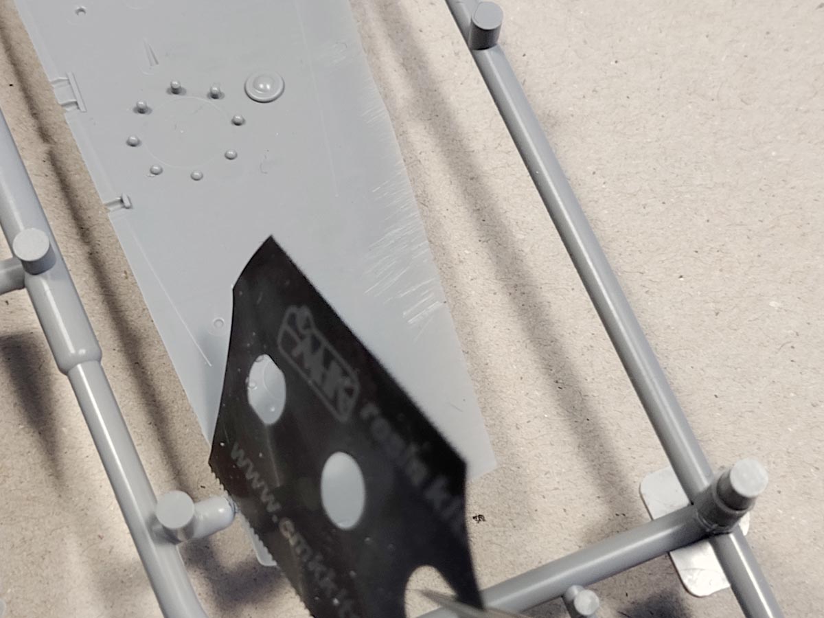
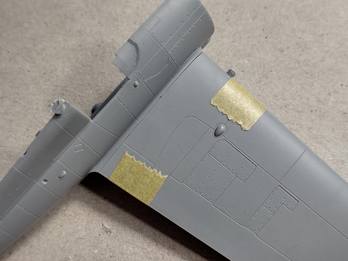
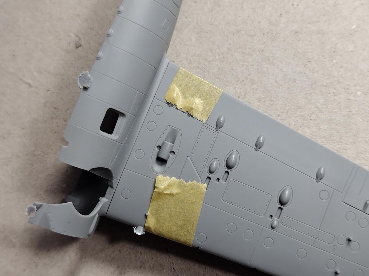
With the help of masking tape, we make two handles that will help to sand on a flat surface. It is worth pressing the part against the paper relatively evenly.

In the fuselage halves, we grind the lower edge of the wing opening with a needle file. In this way, we will enlarge the slot on the side of the lower half of the wing, i.e. the half that we have not ground from inside.
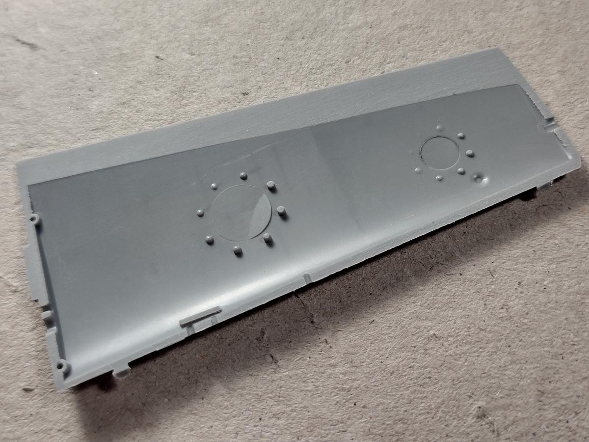
This is how the upper half of the wing looks like after grinding.
And this is how the wing and the fuselage fit after then.
Engine and chassis
Now that we have a minor tweak behind us, I want to show you what can be done in the model.

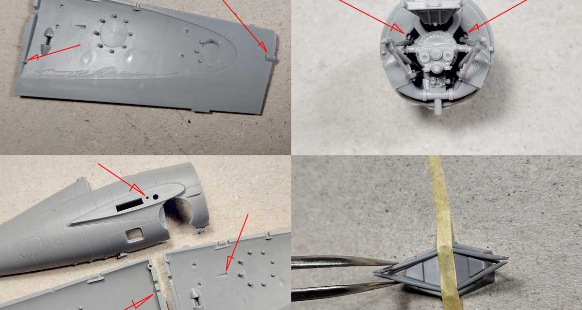
We’ll start with the engine. I made two openings in the firewall that no plastic part would fit.
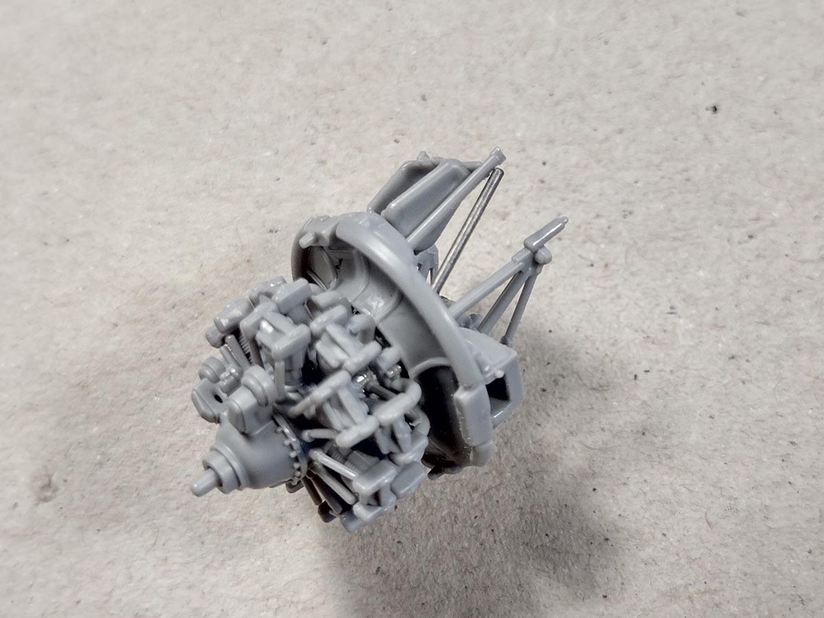
I planned them for an additional element of the engine frame, which you can easily add extra. I didn’t design it as a plastic part to make the design of the compartment behind the engine too complicated. And so we already have a lot of details that require attention during assembly. Therefore, if you manage to assemble the rear of the engine with the frame and you have the ambition to “improve” the manufacturer, you can add two small rods with such dimensions.
It is enough to glue them into the sockets mentioned above and rest them on the frame with the oil tank.
Attention! If it seems to you that the assembly of the motor frame is too much for you, you can safely avoid glueing the frame elements (parts 8, 9, 10) to the model. The whole thing will work the same; all the other parts will have to be assembled anyway.
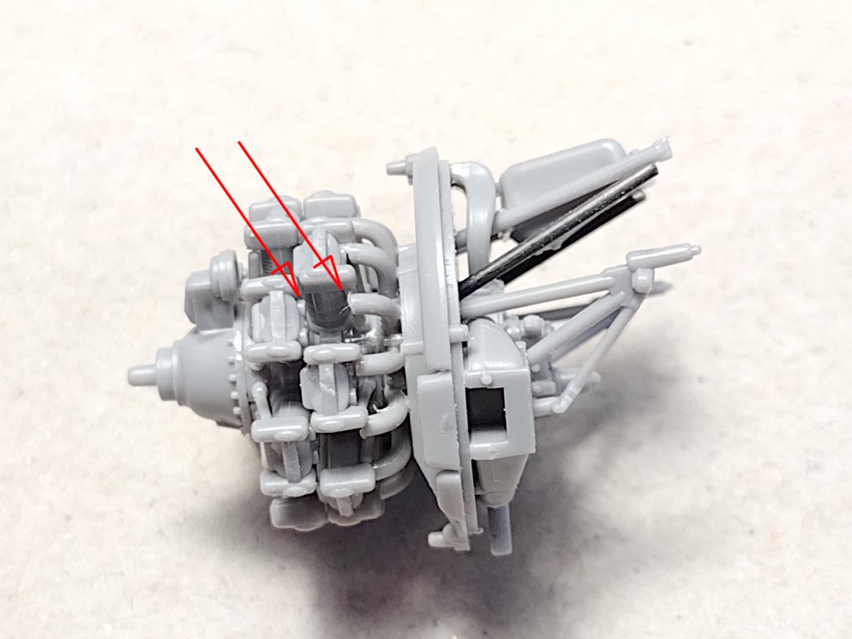
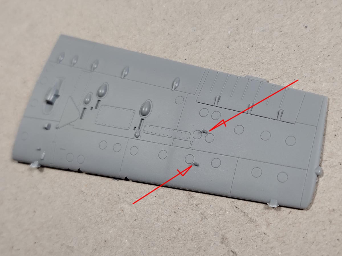
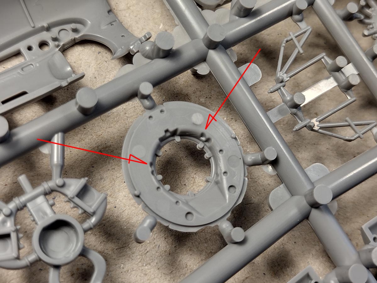
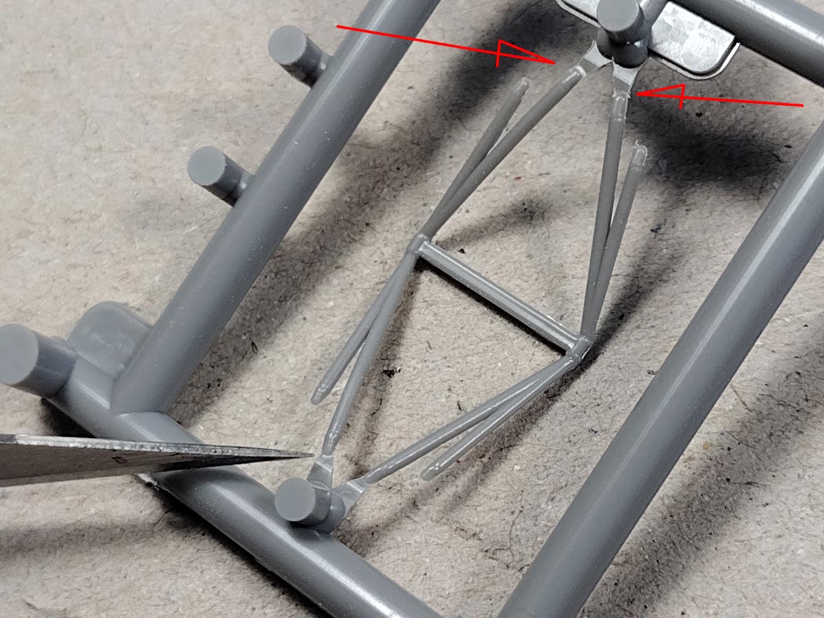
There is one more detail in the engine that you can easily add. These are the mixture inlet pipes at the rear of the engine. They (part 13) are made only to the mounting plate with the rear row for technological reasons. Therefore, the section connecting the inlets with the front star is missing. Don’t worry; it won’t be visible in the finished model anyway. However, if you like to pick at the engine, maybe it is worth adding seven sections of a 1mm rod, each 2.2mm long. The photo shows where they should be inserted (between the arrows)
The last note concerns the pipe going down from the radiator connection in part number 6. This element is visible after the entire engine module is placed in the fuselage. Therefore, it is worth drilling it; in the original, it was a pipe. In the photo, I have marked the tube with arrows before and after drilling.
Let’s move on to the chassis.
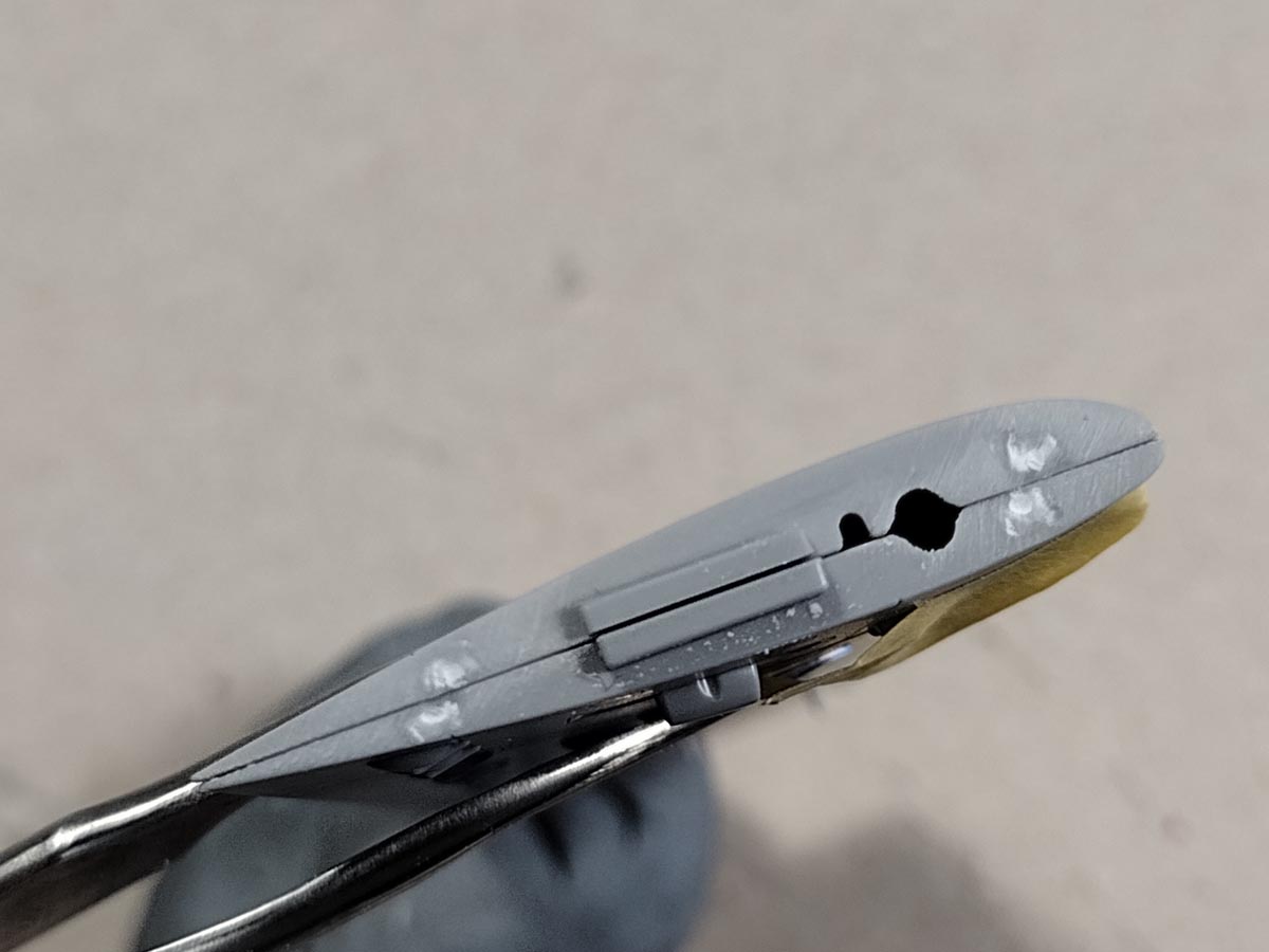
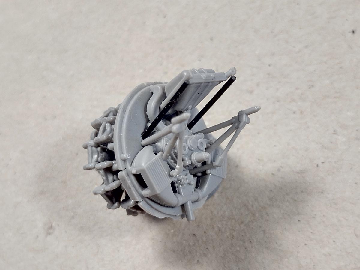
For you, modellers, I found an excellent way to clean parts before assembly. For the whole thing to be easy to handle by hand, it is worth cutting out of the sprue the two most difficult parts together with the surrounding frame.
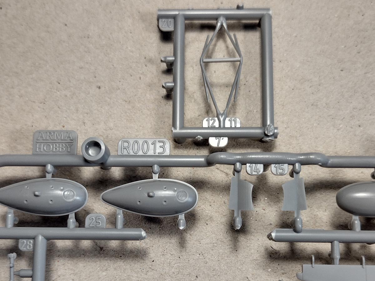
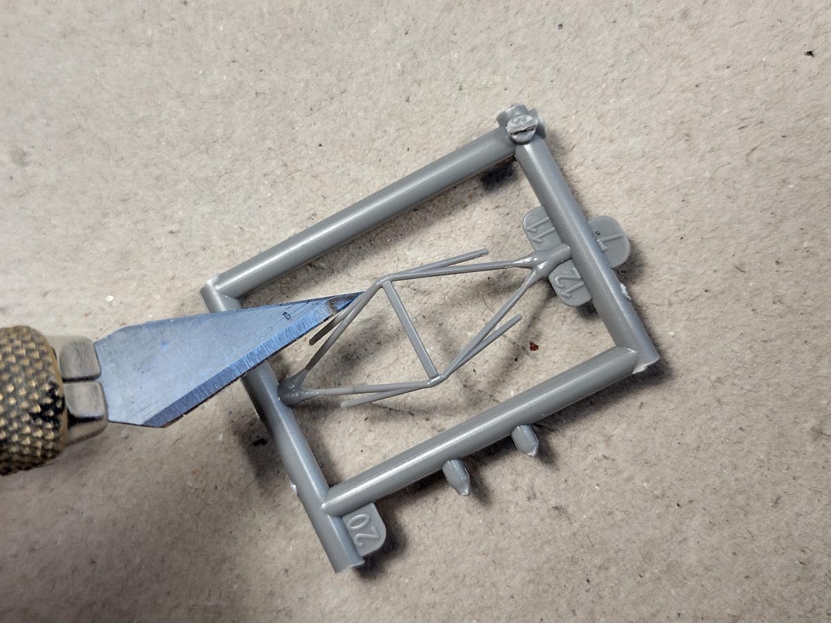
Then clean them with the edge of a scalpel …
And cut it off. Note that the part’s edge is best seen from the bottom, and you should make cuts there. Thanks to this, we will not shorten the part unnecessarily.
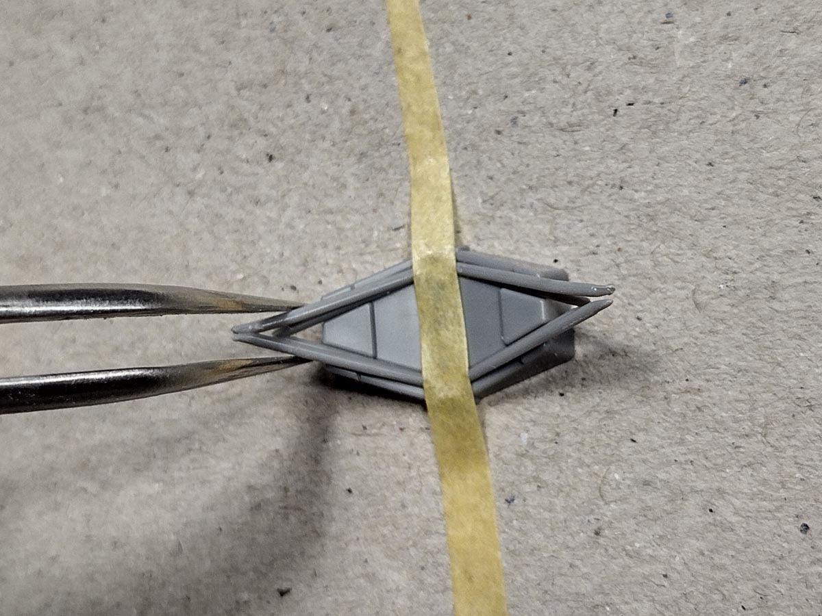
Place both elements in the assembly template and fasten them with a strip of masking tape. Then squeeze the tips with tweezers and apply a small amount of glue.
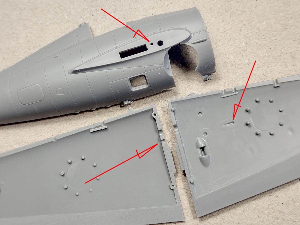

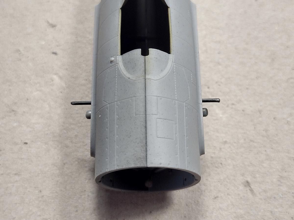
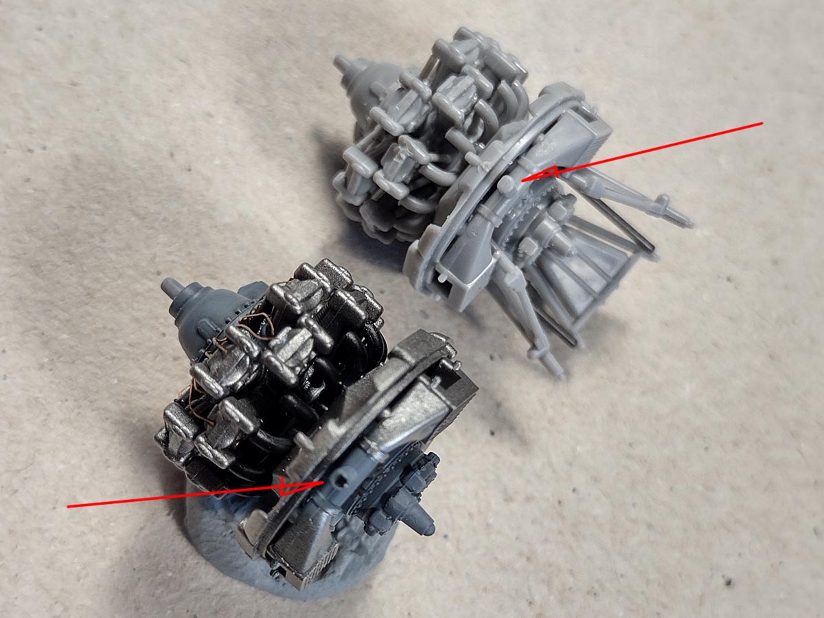
There is another kit feature I wanted to show you, which was already included in the FM-2 model. I prepared the model so that I could add girder through both wings and the fuselage. The photo shows an opening in the fuselage, an incision in the upper half of the wing and a depression in the lower half of the wing. The possible spar does not collide with anything in the pilot’s cabin. And it goes through the complex fuselage. If you want to add such a spar, you need to add a steel or carbon rod with a diameter of 0.8 mm and a length of 56 mm. The spar can also be divided in half and glued to each wing separately, and a tube (eg made of albion alloys) should be glued into the fuselage into which the halves of the “girders” would fit together with the wings.
That’s it on this project. Have fun with the new Wildcat model.
See also:
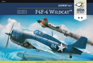
- F4F-4 Wildcat model kits in Arma Hobby Internet shop
Wanted to be Philanthropist, statesman and patron of the arts. Temporarily focused on developing scale model production in Poland. Co-founder of Arma Hobby. Designer of kits: TS-11 Iskra, PZL P.7a, Fokker E.V, PZL P.11c, Hawker Hurricane, Yak-1b, FM-2 Wildcat, P-51B/C Mustang and 1/48 Hurricane.
This post is also available in:
 polski