
The P.11c model has already reached the hands of the first customers. Certainly, some of you have already started cutting parts from the frame or looking for a place in your storage for the box of the new P-eleven in 1/48 scale. For the first ones, I have prepared a small photo guide that will help you get through the cockpit assembly stage without any problems.
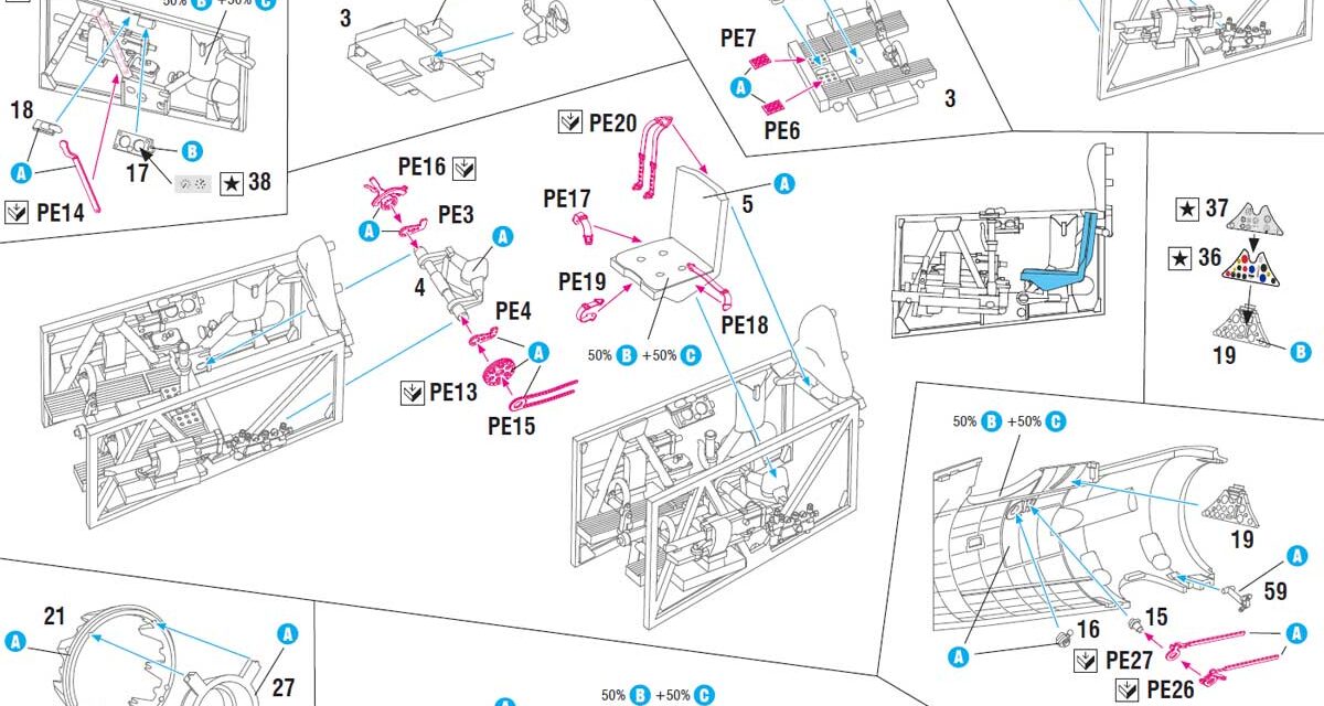
The P.11c cockpit was quite complicated. The inner frame forms a structure that is placed in the fuselage. For clarity, I omitted the photoetched parts in this guide, but I will add a few comments regarding these metal parts in the descriptions.
Let’s start the fun:
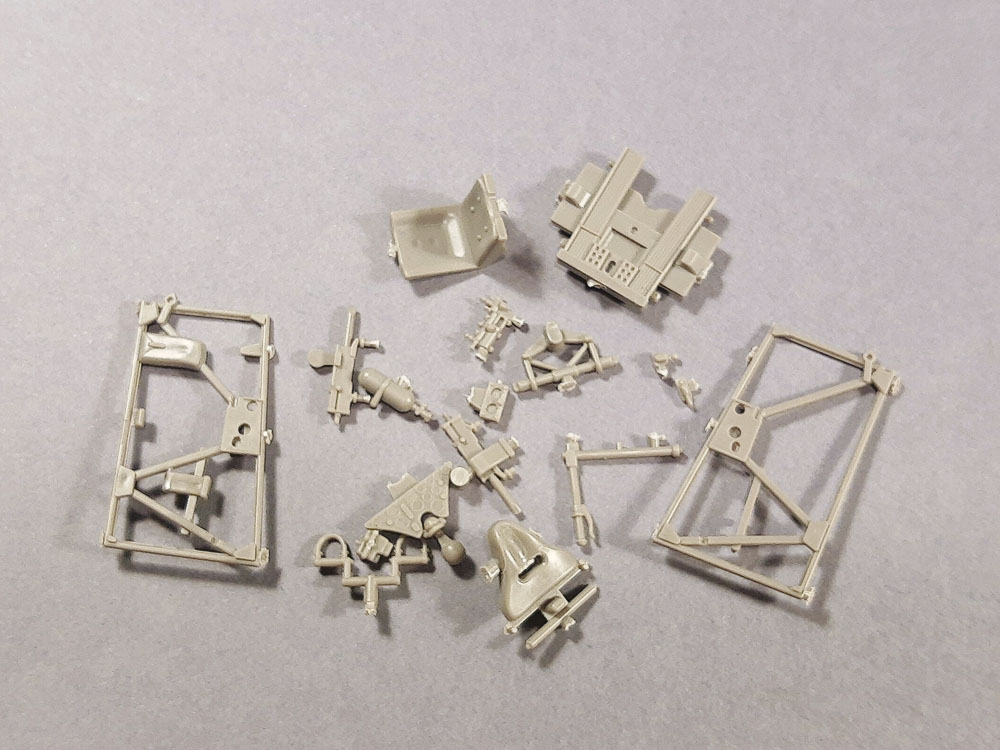
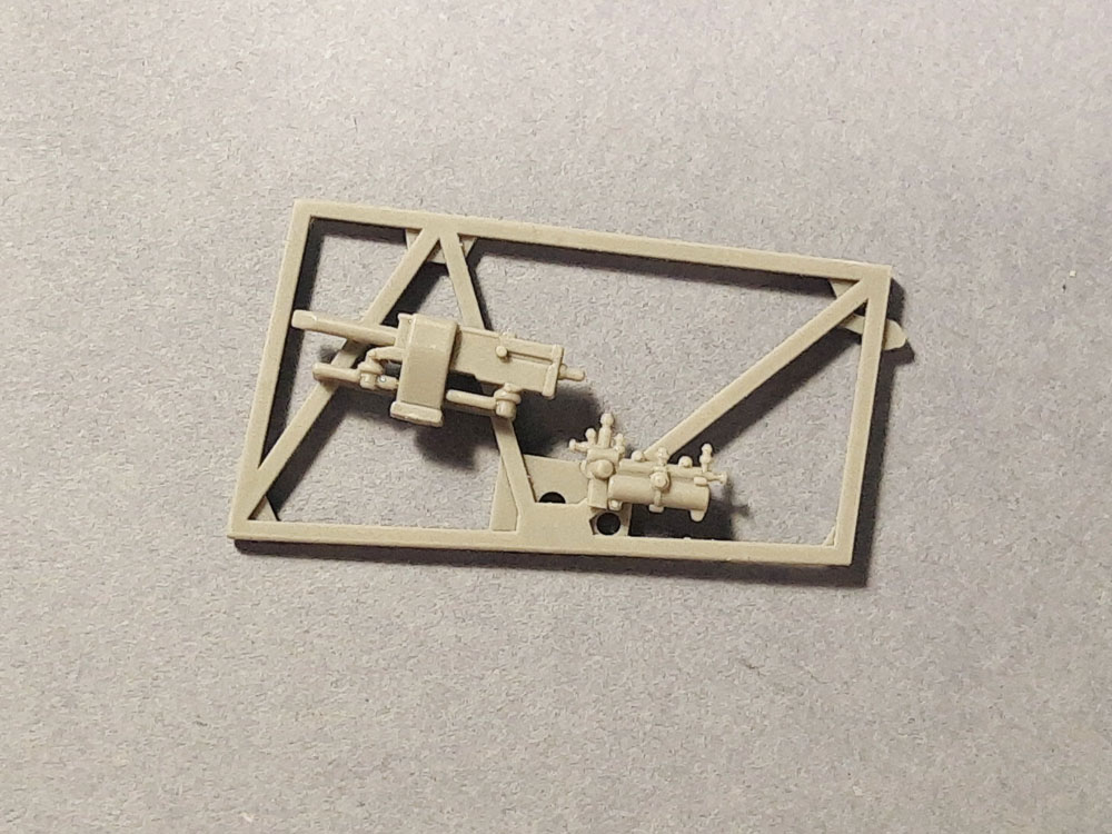
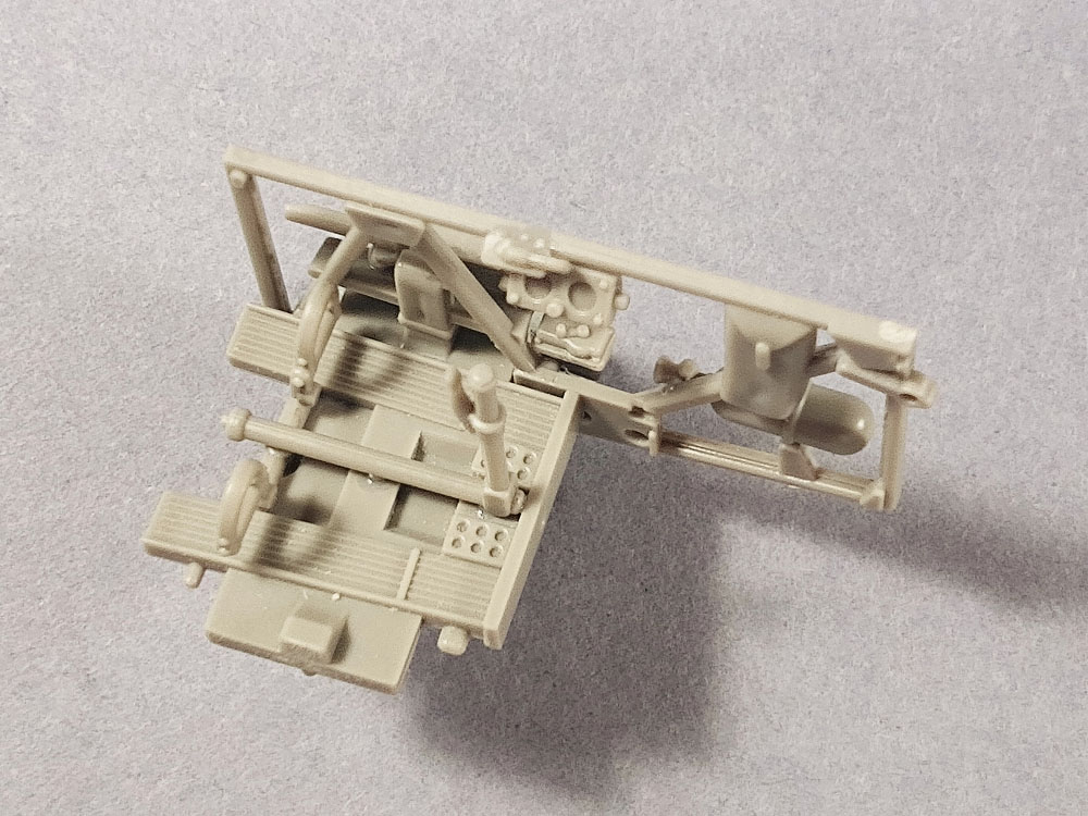
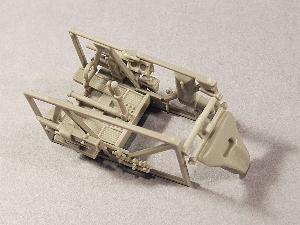
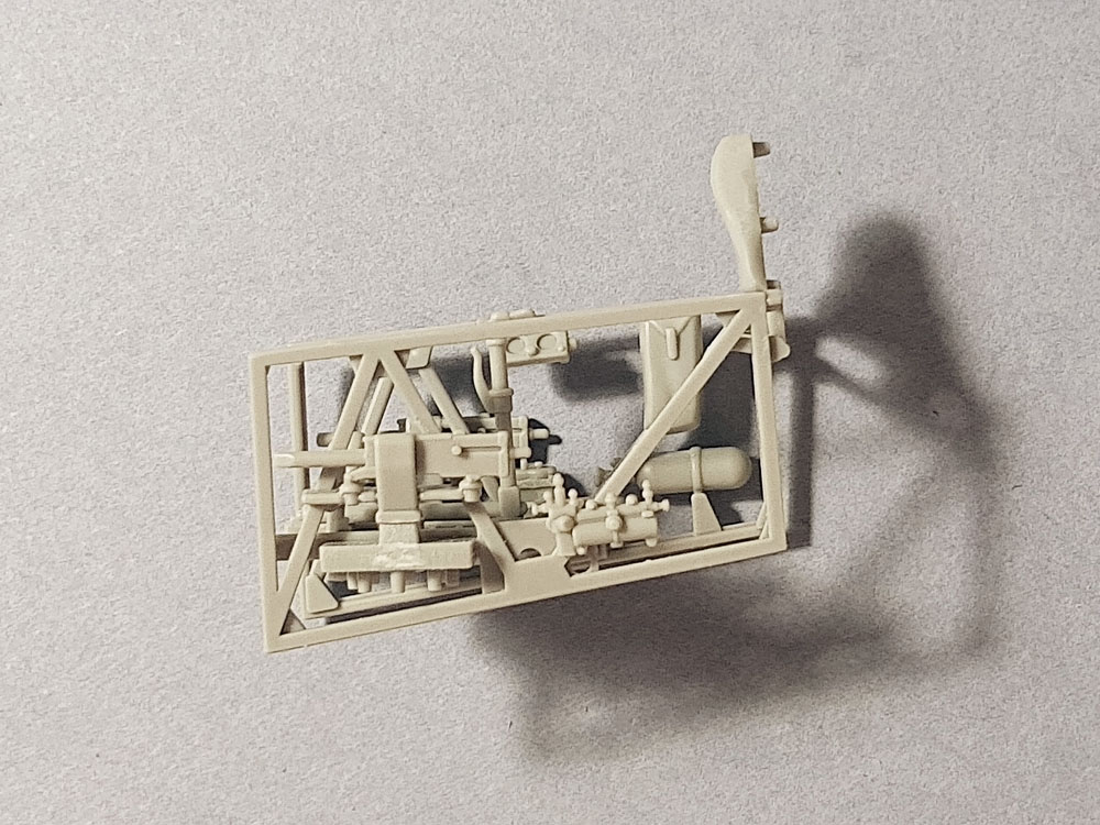
I cut all parts out of the frame

I cleaned the parts with standard modeling tools
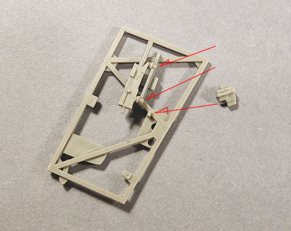
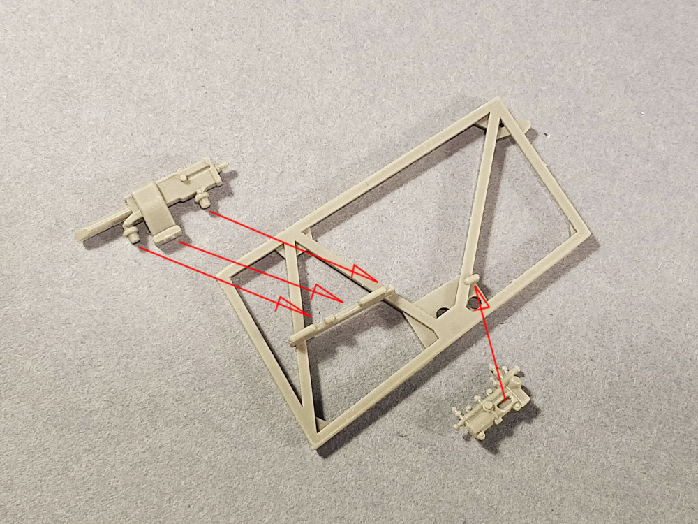
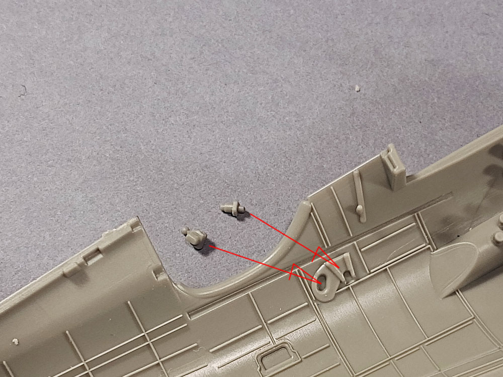
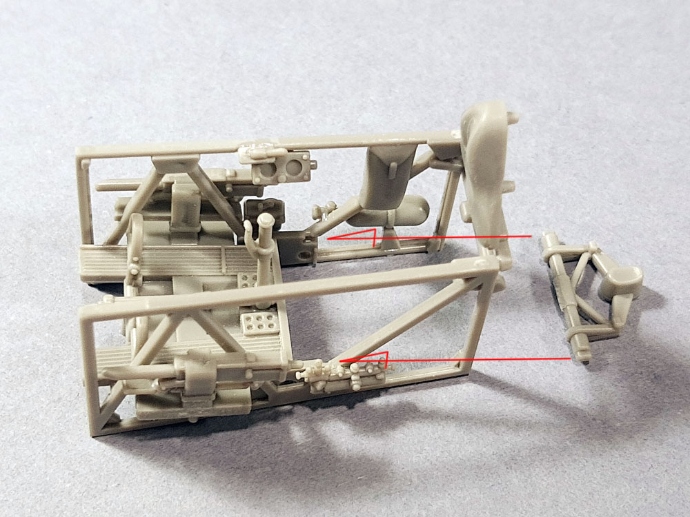
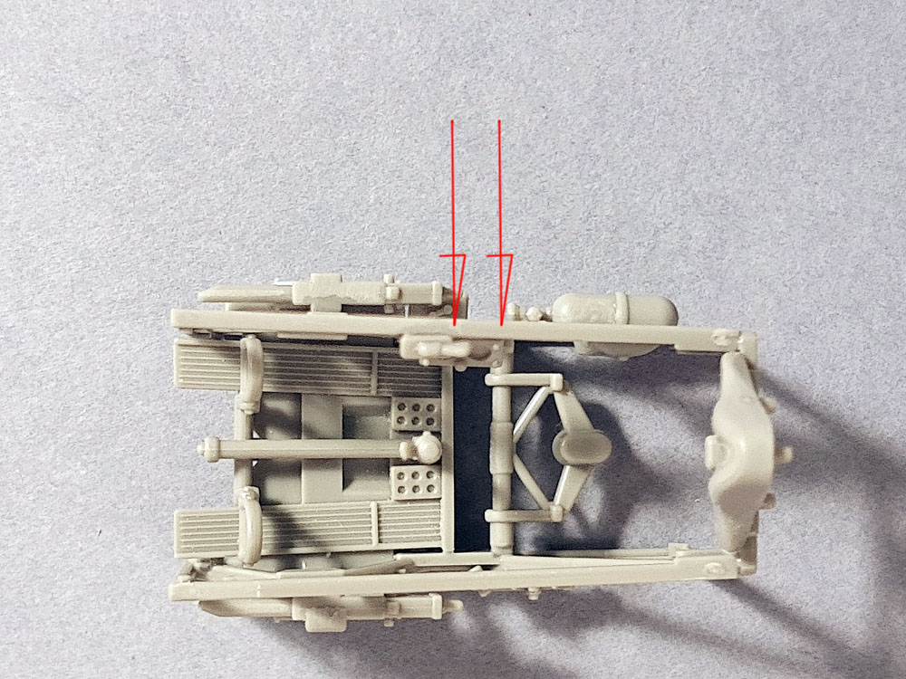
The arrows show where to assembly the parts on the outside of the right frame
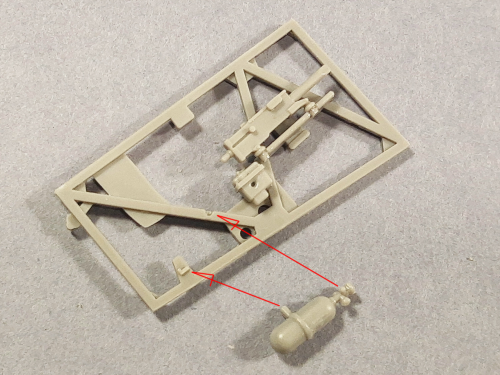
Install the oxygen tank at two points
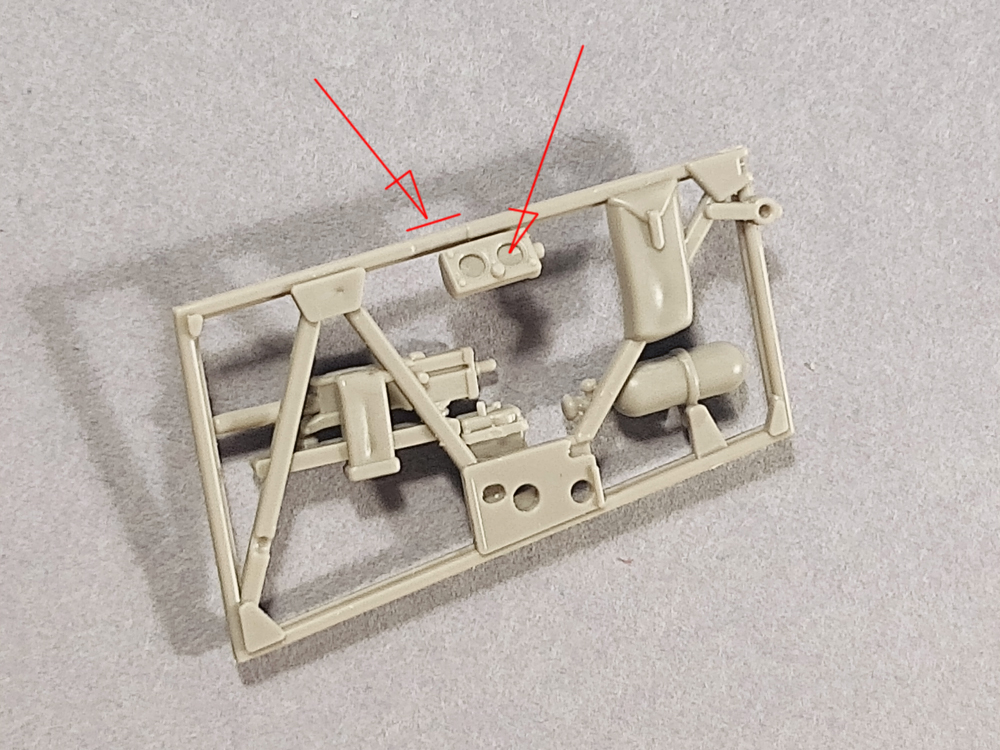
Attach the side panel with two clocks with the small gap to the frame, on the right below of a place for switch-box
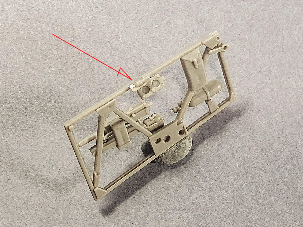
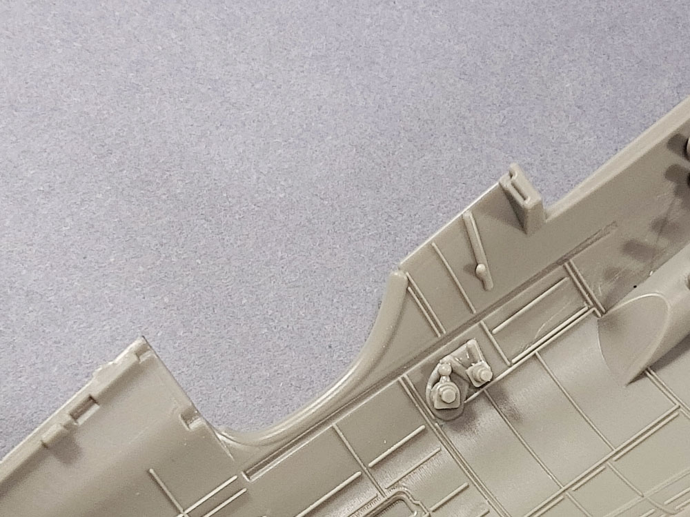
Switch-box in place
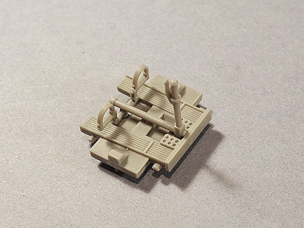
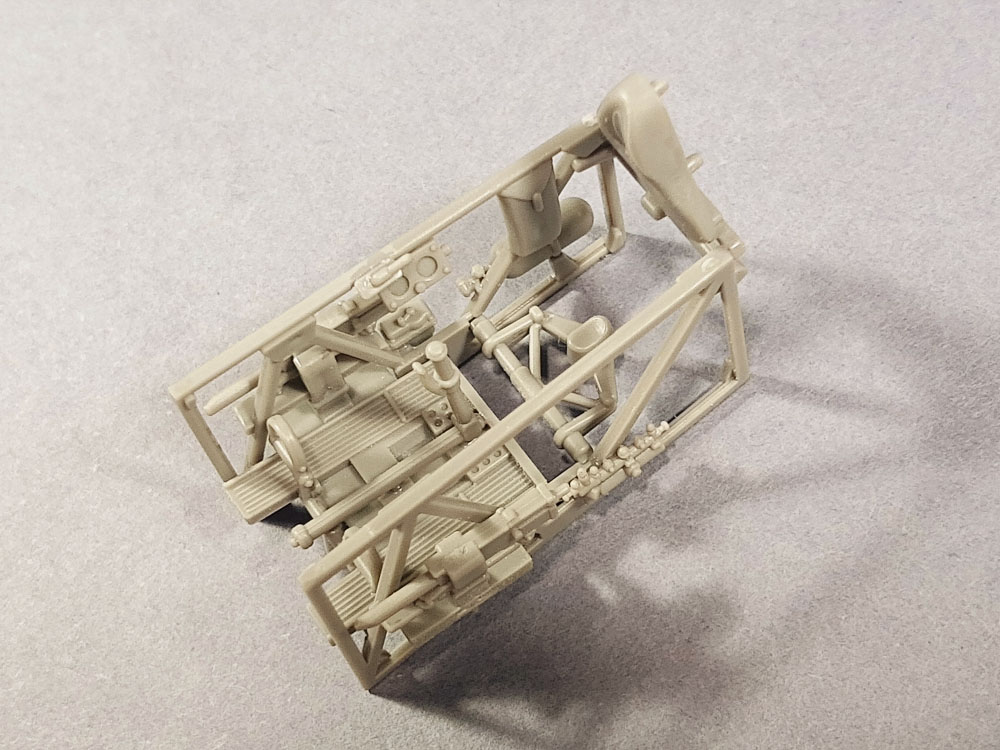
Left frame, outside MG mount and a Viet starter
The left frame is ready

The floor requires sanding the back edge to accommodate the PE13 photo-etched part
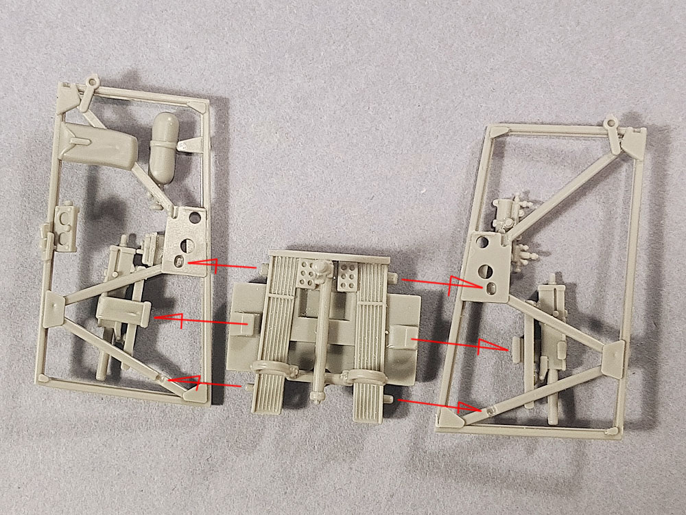
Port side parts attachment points
Parts glued in place
The floor with a control column and ruder pedals assembled
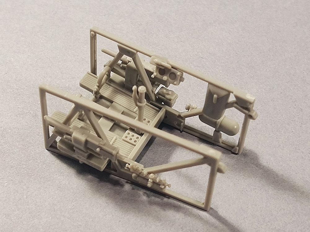
The floor with right and left frames. The places where the parts are joined are marked. It is important that the bottom of the MG (ammunition feed channels) is well cleaned of the sprue runners, thanks to that the sides will come down with the floor at right angles
Right frame glued to the floor

From the bottom you can see parts connection points
And the left frame glued
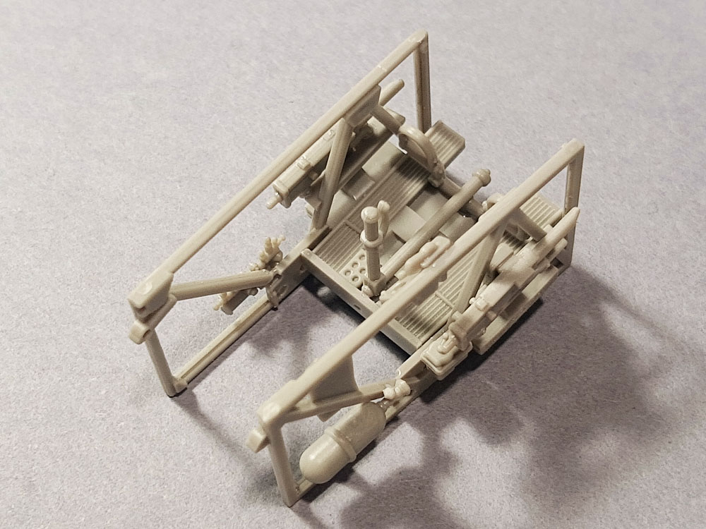
Second shot. It is worth placing the glued module on a flat surface and make sure that both frames are parallel to the plane and, in the front view, perpendicular to the floor sides

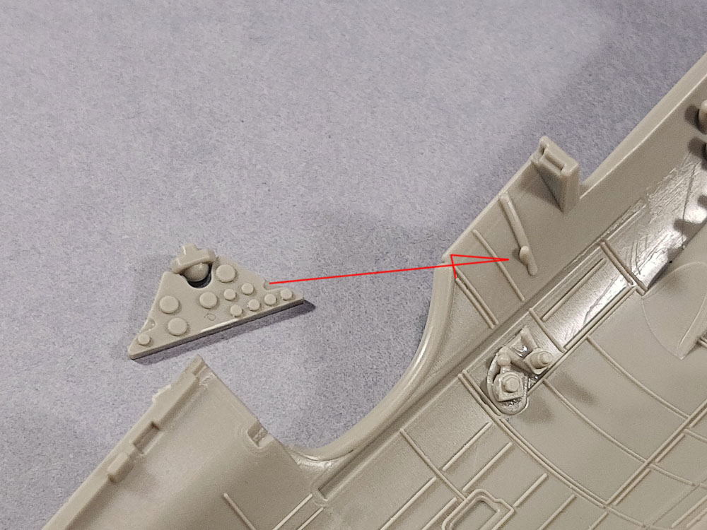
Places for undercutting the headrest as described in the errata (on both sides). It is best to lightly sand the edges after the undercut
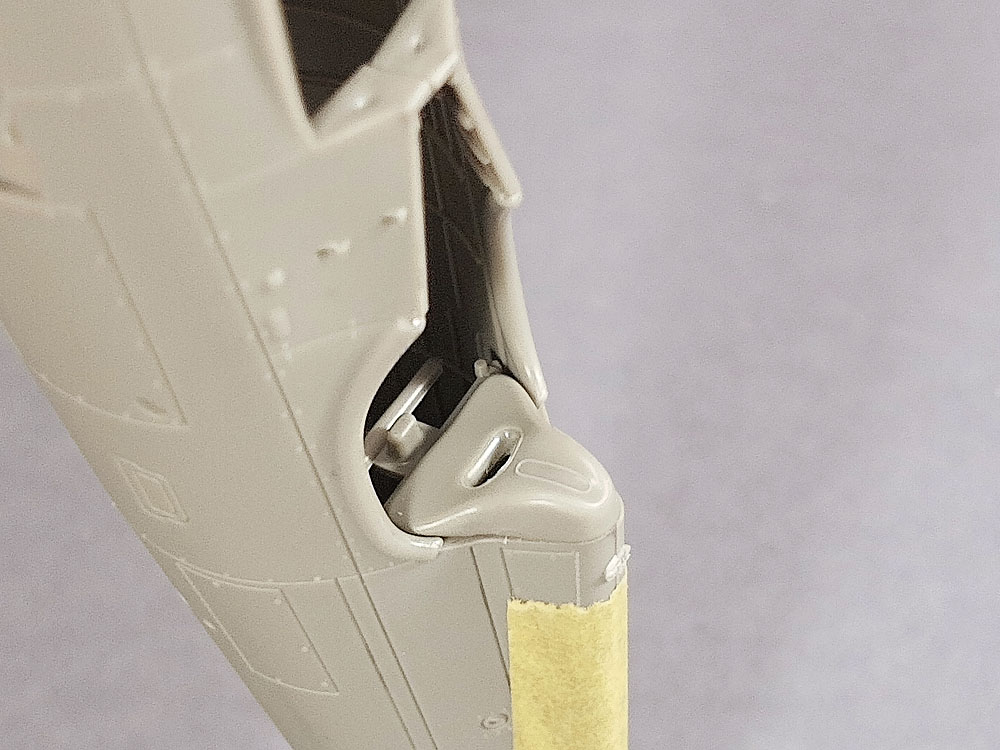
It is recommended to dry fit the headrest and the fuselage. If it fits the outline of the fuselage behind the headrest, it ensures have done the correction well

Headrest attachment points between the right and left frame
After inserting between the frames, rotate the headrest vertically…

…this way
The head restforms a straight line with the rear of the frame
The place of fixing the pilot’s seat base
The base of the seat is glued into place
Pay attention: part flor and seat base should be perpendicular

The seat rests on its base and the lower part of the frame, below the headrest
Place of assembly of the instrument panel
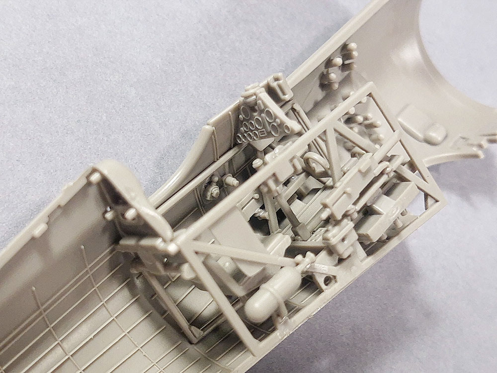
Ready cockpit interior module placed in the fuselage half

Fuselage closed
A few additional comments
All parts should be painted before assembly. The PE16 photo-etched part should just be put on the seat base.Then, after gluing the base between the frames, the PE16 part should be moved as far as possible to the right, up to the side frame. The seat can also be assembedd after building and painting the entire model. This will allow the shoulder straps to be folded outside the cabin, which was often seen in historical photos. PE26 and PE27 gas lever handles can be thickened with a drop of CA or surfacer. The seat can be upgraded by adding two strips connecting the seat with the backrest. Avid modelers can make some extra cables here and there in the cabin based on the photos of the original. I described thow to easy make the instrument panel in the previous post.
See also:


- P.11c Expert Set 1/48 and more in Arma Hobby webstore klik
This post is also available in:  polski

